TL082CN Non Inverting Amplifier

Thread Starter

cookieplz

Joined Apr 23, 2017
8
Hi All,

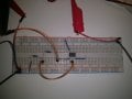
I am trying to put together a non inverting amp with a gain of 10.

I put it together using a 10k and 100k resistors and the opamp input voltage at 14V form a power supply.

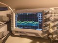
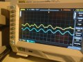
The input signal is fed from a function gen as a sine wave @100Hz and 200mVPP. I breadboarded all of this, but my issue is that the output signal looks horrible, with no signs of it being amplified. I am sure I am doing something horribly stupid, but I could use some insight.

I have attached a couple of photos of the input/ output signals and the breadboard, any help would be appreciated
 

Attachments

crutschow

Joined Mar 14, 2008
34,459
As MC noted you need a dual power supply (or you need to apply a DC offset of at least +4V to the signal.)
Alternately you could use a rail-rail type op amp.
 

Thread Starter

cookieplz

Joined Apr 23, 2017
8
Got it.

So I added another power supply channel and connected them as such :

I connected the negative lead of the first channel to the positive terminal of the second channel.

I then connected the negative of the second channel to VCC-
And the positive of the first channel to VCC+

With respect to the negative of the first channel VCC+ = 10V VCC- = -10V. But the waveform still looks about the same, I can take another picture
 

DickCappels

Joined Aug 21, 2008
10,185
Are your power supplies clean? Did you use the capacitors across the power supplies as absf showed in post #7?

If they are already there, try 100 uf.
 

Thread Starter

cookieplz

Joined Apr 23, 2017
8
I did not have the power supply capacitors :(.

I think things are mostly working now, but I see some bizarre behavior.

If I sweep the frequencies of the input signal from 100 Hz to 1Khz and turn on the voltage to the opamp, the output signal behaves as you would
expect. However after a few seconds I see the following yellow output signal:

Any ideas on what could be causing this?
 

Attachments

AnalogKid

Joined Aug 1, 2013
11,055
Since you know how to post a photo, draw your schematic on a piece of paper. Show every component, every power supply, every signal source, every scope connection, and every component connection. Make sure each component has a unique reference designator. Take a picture. Post it.

ak
 

absf

Joined Dec 29, 2010
1,968
You need one more wire from the centre of the 2 power supplies to the -ive side of the sig gen.

IMG_20170423_221424.jpg

If you're using TL082, I think pin 4 and pin 8 are backwards. Let me check with pdf again.

Allen
 

MrAl

Joined Jun 17, 2014
11,489
Hi,

Yeah, floating input :)

But remember one more little thing...
The gain of a non inverting amp is not R2/R1 it is R2/R1+1. Note that +1 there.
That means with a 10k resistor and 1k resistor the gain is not 10 it is 11.
Likewise, with 10k and 2k it is not 5 it is 6 because we have to add 1.
 
Top