inverting summing amp (revisited)

Thread Starter

Homebrew1964

Joined Nov 22, 2024
160
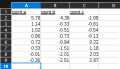
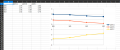
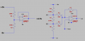
So i found some time this week to play with my Inverting summing amplifier circuit, i changed the 10K input resistors to 5K6 which didn't make any difference, then i played with the value of R6, i started with 1K6 and gradually dropped the ohmic value till i got to 1K2 and i got the expected results, anything below 1K gave me screwy results again, i don't have any 1K1 resistors so i don't have a result for that value but it does seem that everything is as expected untill i bring point b to zero volts i.e i get the two input voltages added together and the output giving me the minus equivalent, as soon as i bring point b to less than 0V my output starts to not make sense...my readings are all taken relative to pin 3 of the LM358 (4.5V virtual ground)

Can anyone tell me why please?

i hope my description makes sense.

EDIT: I have been giving this some thought and have realized that when one input is positive and one input is negative, that is when i get a goofy output, it is only when both inputs are of the same polarity that i get a good result.
 

Attachments

Last edited:

ronsimpson

Joined Oct 7, 2019
4,664
I am not clear as to your problem. There is a limitation on that op-amp that you might not be clear on. The inputs do not work then they get too close to the supply voltages. In your case you should measure the supply at +4.5 and -4.5V. If the input gets to +3V or -3V the IC may act wrong. (Worse case +/-2.5V) Or to say it in a different way the inputs should not be used with in 1.5V of the supplies. ( Could be as bad as 2V from supplies. )
 

Thread Starter

Homebrew1964

Joined Nov 22, 2024
160
I am not clear as to your problem. There is a limitation on that op-amp that you might not be clear on. The inputs do not work then they get too close to the supply voltages. In your case you should measure the supply at +4.5 and -4.5V. If the input gets to +3V or -3V the IC may act wrong. (Worse case +/-2.5V) Or to say it in a different way the inputs should not be used with in 1.5V of the supplies. ( Could be as bad as 2V from supplies. )
ok Ron, thanks for the heads up on that.

The problem i was having was that i had to have both inputs the same orientation (either both positive or both negative) or else the output would get confused, positive inputs produce a negative output and vice versa.
 
Last edited:

WBahn

Joined Mar 31, 2012
32,777
Once again, you are making every one guess. Not only do we have to guess what you expected to see, but also guess at what you actually saw (for the "screwy" cases). All we have to work with is that some of your results are "screwy" and "goofy". Well, with only that to go on, the best we can do is tell you that the most likely cause is that it is your expectations that are messed up. But since you won't give us that information, we have no idea if that's the case or not.

Give us a table like the following:

Code:
           EXPECTED (V)      MEASURED (V)
R6 (kΩ)   V(a) V(b) V(c)   V(a) V(b) V(c) 
   1.6
   1.5
 

WBahn

Joined Mar 31, 2012
32,777
I am not clear as to your problem. There is a limitation on that op-amp that you might not be clear on. The inputs do not work then they get too close to the supply voltages. In your case you should measure the supply at +4.5 and -4.5V. If the input gets to +3V or -3V the IC may act wrong. (Worse case +/-2.5V) Or to say it in a different way the inputs should not be used with in 1.5V of the supplies. ( Could be as bad as 2V from supplies. )
Shouldn't come into play here, since the values of V(a) and V(b) are never seen by the op-amp. The non-inverting input is fixed at 0 V (relative to his virtual ground), which is 4.5 V away from either rail. So, until the op-amp saturates (at about -4.4 V and +3.1 V), the non-inverting input will be driven to that same voltage.
 

WBahn

Joined Mar 31, 2012
32,777
ok Ron, thanks for the heads up on that.

The problem i was having was that i had to have both inputs the same orientation (either both positive or both negative) or else the output would get confused, positive inputs produce a negative output and vice versa.
Then why won't you give us an example of the case where you have inputs of "opposite orientation", since that's the case that is troubling you?
 

WBahn

Joined Mar 31, 2012
32,777
See post #3
That's the problem you said you were having, not the solution that you found (unless the solution was to just limit yourself to only operating the circuit in subpart of it's actual range just because it isn't doing what you expect it to do, regardless of whether the problem is the circuit or your expectations).

There should be no problem with inputs of opposite polarity (relative to your virtual ground).

For instance, if you make R6 750 Ω (i.e., the same as R4), you should have equal and opposite inputs and your output voltage should be close to 0 V (i.e., equal to your virtual ground voltage).

What voltage do you actually get?
 

Thread Starter

Homebrew1964

Joined Nov 22, 2024
160
That's the problem you said you were having, not the solution that you found (unless the solution was to just limit yourself to only operating the circuit in subpart of it's actual range just because it isn't doing what you expect it to do, regardless of whether the problem is the circuit or your expectations).

There should be no problem with inputs of opposite polarity (relative to your virtual ground).

For instance, if you make R6 750 Ω (i.e., the same as R4), you should have equal and opposite inputs and your output voltage should be close to 0 V (i.e., equal to your virtual ground voltage).

What voltage do you actually get?
I'll try that later and let you know
 

Thread Starter

Homebrew1964

Joined Nov 22, 2024
160
I just tried it and yes, my output was 14mV....this is exciting, I will play more later, it's 1am here in the states and I need sleep

Thank you.
 

Thread Starter

Homebrew1964

Joined Nov 22, 2024
160
Then why won't you give us an example of the case where you have inputs of "opposite orientation", since that's the case that is troubling you?
ok this is what i came up with to best explain what i am not understanding.

I replaced R6 with a 1K potentiometer, i adjusted the pot taking readings at the 3 various points as i did so, the table explains my results.

I was on the understanding that this inverting summing amplifier would give me the sum of the two inputs but at the opposit polarity but i see i have in some instances a negative input AND a positive one so how is the op amp supposed to know whether to output a minus or a positive number.
 

Attachments

WBahn

Joined Mar 31, 2012
32,777
ok this is what i came up with to best explain what i am not understanding.

I replaced R6 with a 1K potentiometer, i adjusted the pot taking readings at the 3 various points as i did so, the table explains my results.

I was on the understanding that this inverting summing amplifier would give me the sum of the two inputs but at the opposit polarity but i see i have in some instances a negative input AND a positive one so how is the op amp supposed to know whether to output a minus or a positive number.
The nominal output is simply

V(c) = -(V(a) + V(b))

So just add the two input voltages together and then flip the sign on the result, whatever it happens to be.

But, in your table, how are you getting a value of 5.79 V for V(a) on the first line when your max voltage is 4.5 V.
 

Thread Starter

Homebrew1964

Joined Nov 22, 2024
160
The nominal output is simply

V(c) = -(V(a) + V(b))

So just add the two input voltages together and then flip the sign on the result, whatever it happens to be.

But, in your table, how are you getting a value of 5.79 V for V(a) on the first line when your max voltage is 4.5 V.
Thank you... thank you... thank you....
i tried that formula on a couple of lines in that table and it works out to the last digit....WOW!!!

As for the first line i don't know what happened, i will recheck that one.

EDIT: I rechecked line one and it should read a)1.26V and B)-0.17V I must of had a brain infarct lol

thanks again.
 
Last edited:

WBahn

Joined Mar 31, 2012
32,777
Thank you... thank you... thank you....
i tried that formula on a couple of lines in that table and it works out to the last digit....WOW!!!

As for the first line i don't know what happened, i will recheck that one.

EDIT: I rechecked line one and it should read a)1.26V and B)-0.17V I must of had a brain infarct lol

thanks again.
Glad that helped. And hopefully you can see how important and valuable it is to give us both what you expect and what you actually measure. In this case, we could have spotted immediately that the problem was with what you were expecting to see. We simply are not mind readers and can only work with what you give us.
 
Top