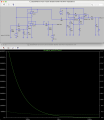
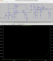
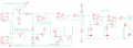
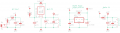
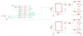
Thought about it a little more and using C3 (10uF) is to achieve near zero (or zero) ideal output impedance for a guitar pedal buffer. If the 10uF is removed, the output impedance, instead of mostly flat, turns into this:
Using the 2nd TL072 opamp for just the MCP6002 side of the circuit cuts down on two resistors (the 100R resistors that make the parallel opamps share the load). But yeah, you're right, I don't know if we need to join them. I mean, after all, we're building a tuner pedal and not a buffer.
But, I figure, if we're going to include a buffer (so that it's possible to do monitoring ... i.e., have the tuner displaying pitch while playing through an amp), it might as well be pretty decent.
Which option would be "best"? I don't know. I think if they are in parallel, it'd give someone the option to use the pedal at the end of the signal chain or ... drive a bunch of true bypass pedals if it's the first pedal, more than if it was just a single opamp.
Is there a big benefit for keeping them separate, other than saving two 100R resistors?
So we can save two 100R resistors and keep them separate. That's no problem. I kind of like the idea of having them separate anyway because it gives the MCP6002 a buffer completely independent. In this case, the only reason for using the 2nd buffer is to keep the input impedance at 1M instead of loading down the impedance with the MCP6002 part of the circuit.
Your problem is the input impedance of the circuit.
You have an input impedance of just under 50k (100k, 100k and 1Meg in parallel). Most guitar amps have 1Meg. The ideal is about 220k.
The pickup is modelled as 6k series resistance and 6H inductance. The cable capacitance is modelled as 220pF View attachment 347496Green is 50k, blue is 1Meg and red is 220k.
You can see that the interaction between the pickup inductance and the cable capacitance causes a big peak in the treble with 1M, which gives it a bright sound.
50k attenuates the treble and removes the peak.
220k is about neutral.
Circling back to this…are you saying that ideally, for a flat signal (or keeping the guitar signal as close to original as possible), you’d want to shoot for having an input impedance of about 220k instead of 1M?
@LowQCab hope you don’t mind me circling back to your post asking for a few bits of clarification now that I think I understand parts of the circuit more.
~100Hz is the absolute lowest-Frequency that these RC-Networks, ( Input-Filters ),
need to pass for a standard 6-String-Electric-Guitar-Stomp-Box.
Most commercial Stomp-Boxes start Rolling-Off at around ~200Hz or sometimes even higher.
Bass-Frequencies are generally considered "unwanted-Noises" from an Electric-Guitar,
and can seriously "mess-with" what an "Effects-Box" is trying to achieve.
You don't want Low-Frequency "Noise" causing
Intermodulation-Distortion, ( IM-Distortion ), of Higher-Frequencies.
"IM-Distortion", "can be", very desirable when caused by Frequencies, ( Notes ),
that the Guitar is normally designed to produce,
the lowest of which is ~82Hz, or "E-2",
( if the Guitar is not "Tuned-Down" for special effects ).
But when it comes-down-to creating an excellent sounding "Final-Mix",
each Instrument needs to have "It's-own-Space" in the Mix,
and not "stomp-on" any of the other Instruments, ( like the Bass-Guitar ).
That final excellent "Tone" that You may be able to create while practicing,
may sound like warmed-over-crap when put into the context of an entire Band playing together.
Musicians tend to have some rather strange, ( for a Recording-Engineer ), vocabulary for describing
what an Instrument "Sounds-Like".
When You say it sounds "Dark" or "muffled" that may-well actually be too much Bass in the "Tone",
rather than the High-Frequencies being excessively Attenuated, or Rolled-Off.
Ok, I think I get what you’re saying. In this case, at least for the tuner, I’d like to get all the frequency info as possible to it’s possible to tune lower instruments like 5-string bass, etc. On dropping into the mix I get it, though I’m not sure in this case a tuner should be filtering content out?
You don't need 2-Gain-Stages,
You currently have a Gain of around 600X going into your Computer-Input,
with a ~5-Volt Power supply, You are sending your Computer a HARD-CLIPPED-SQUARE-WAVE at all times,
I'm guessing this was not your original intention.
Did You calculate whether or not your TL072 could easily drive the Input-Resistance that You chose ?
The TL072 is an "Old-Skool" Low-Noise, Audio-Op-Amp that must have a
fairly High Power-Supply-Voltage to not be
trouble-prone and clip like crazy, and become somewhat unstable.
I would pick a much more modern Op-Amp for your application,
You don't need to be too concerned about Low-Distortion, but Low-Noise is always nice.
The TL072 is an excellent Audio-Op-Amp, but only when it has close to a ~20-Volt-Split-Power-Supply.
Roger that. I guess we chose it because it seems to be a pretty popular opamp used in buffers running at 9V and we can get them cheap, but I understand what you’re saying. It doesn’t have much voltage swing at 9v at all. I’ll be testing out some more expensive opamps this week I hope.
Well ..........
when I wrote the above stuff,
I completely "missed the Boat" on what the project was intended for,
I though it was an Effects-Box of some strange sort.
.
.
.
Well ..........
when I wrote the above stuff,
I completely "missed the Boat" on what the project was intended for,
I though it was an Effects-Box of some strange sort.
If I were to change C3 to 47uF (low ESR) electrolytic cap, would that adversely affect anything? It looks like from the LTspice simulation, the output impedance gets a bit better (closer to zero at lower frequencies). I tried it on my breadboarded circuit and it seems just as good as with 10uF. Just wondered if it'd be worse for transients or anything odd like that?
If I were to change C3 to 47uF (low ESR) electrolytic cap, would that adversely affect anything? It looks like from the LTspice simulation, the output impedance gets a bit better (closer to zero at lower frequencies). I tried it on my breadboarded circuit and it seems just as good as with 10uF. Just wondered if it'd be worse for transients or anything odd like that?
@joulupukki has done a lot of work on this lately, I've been lurking in the background. But we are ready for the next prototype, which hopefully will be good for production. If anyone has any further suggestions, please do.
Couple questions:
1) Are 1N5817 diodes really needed across the regulators in the PS Section?
2) C7 and C8 in the Audio buffer section are in the direct audio signal path. C7 is film. But for C8-47u, I wasn't sure what to use so I chose electrolytic-low-ESR. ???
3) We recently upgraded the regulators from L7805 and L78L05 to LDO's hoping to reduce the noise. Comments on this?
4) The regulators recommend low-ESR output caps, I'm not sure it's necessary for our application. Any downside to using them anyway?
I still question the value of C8, seems rather large.
Does the buffered output connect directly to the amp or are other pedals involved?
For low ESR I generally use tantalum caps.
I still question the value of C8, seems rather large.
Does the buffered output connect directly to the amp or are other pedals involved?
For low ESR I generally use tantalum caps.
The buffered output can connect to either of those, however someone will want to use this pedal. Ideally it should work in both places. I've seen 10uF common on the output for buffer pedal schematics. I tried 47uF out and it seemed to sound the same as 10uF. We were just thinking if we used a 47uF low-ESR cap for the other locations, we'd use the same flavor here?
We have a new set of prototype boards where we can play with RPDO, C7, and C8. Right now I have mine wired up as shown in the schematic with C8 at 47uF but I’m getting a pretty big pop every time I switch between buffered bypass and tuning mode (when IC5 - Relay switches).
Now I’m wondering if it’s possible that‘s because of the 47uF in that position? I know in AMZ’s super buffer he was using a 10uF. In an earlier version we were using a 100K pull down resistor and right now I’ve tot the 2M installed.
The tube screamer's buffer uses 10u+10k.
What exactly does the value of the output pull down resistor do and is there any benefit of using 10k vs 100k? Anyone know?
it determines how long it takes to charge the output capacitor to half supply.
Without a pulldown resistor, the input impedance of the next stage charges the capacitor, and that could result is a sizeable switch-on thump.
it determines how long it takes to charge the output capacitor to half supply.
Without a pulldown resistor, the input impedance of the next stage charges the capacitor, and that could result is a sizeable switch-on thump.

 Facebook
 Google
 GitHub
 Linkedin