The TIP42 in bridged class ab amp is hot.

Martin_R

Joined Aug 28, 2019
137
TS needs to understand that the emitter resistor is an inexpensive way of applying negative feedback and hence reduce crossover distortion.
My understanding was the emitter resistor provides negative feedback for thermal compensation as it's main purpose, rather than crossover distortion, which is a bonus
 

Ian0

Joined Aug 7, 2020
13,228
My understanding was the emitter resistor provides negative feedback for thermal compensation as it's main purpose, rather than crossover distortion, which is a bonus
It’s about keeping the bias stable. With two transistors and two diodes, you have four junctions of unknown voltage, so the outcome is rather unpredictable, especially as the transistors tend to get hotter than the diodes and Vbe varies with temperature.
Use three diodes in series to set the reference, and emitter resistors, the bias becomes much more predictable, being about 0.6V/2R where R is your chosen resistor value. If the diode voltage varies between 0.55V and 0.7V then the bias varies but it doesn’t vary much.
 

Thread Starter

mike_canada

Joined Feb 21, 2020
239
I have made those amplifiers before but In the end I'm trying to achieve good volume.
So far, my best was an amplifier similar to one pointed out by a recent circuit that someone showed, but the sound could only travel up to 2 meters outdoors and that's with using my mini 2" 4W speakers. Now I have 4" 20W speakers and I should make better use then 2 meters.

I take it that quiescent means standby current (where no music plays at input) and that I should make that set so that the used wattage is < 1 for better operation.

If I can get my circuit to achieve that and maybe even play sound at a 4 meter distance, without raising the voltage, then I'm golden.
 

Audioguru again

Joined Oct 21, 2019
6,826
With a 7.2V supply powering your bridged amplifier circuit, the max output without clipping is about 12.8V peak-to-peak.
12.8Vp-p converts to 4.53V continuous RMS.
4.53V RMS produces continuous 2.57W into 8 ohms or 2.63W into the 7.8 ohms of your speaker. Fairly low power.
Peak power is momentary (not continuous) and is simply double the real power and is used in advertising lies.

Your two amplifier halves must be biased so that their output is symmetrical and does not have the top or bottom of the waveform clipping.

Your simple circuit changes its biasing when the supply voltage drops that does not happen in an IC or proper discrete circuit design.

The output transistors in a class-AB amplifier like yours should idle at 20mA to 30mA then produce no crossover distortion.

Emitter resistors on the output transistors will reduce the idle current a little but not enough and will also reduce the max output power.
Those emitter resistors without the biasing diodes will produce plenty of crossover distortion since your circuit does not have enough open loop voltage gain for negative feedback to reduce the distortion.
 

Thread Starter

mike_canada

Joined Feb 21, 2020
239
So is my problem then that I can't make the voltage difference in spice higher than the total RMS voltage without asking for wasted power? and I'm guessing peak to peak voltage was calculated from twice the supply voltage minus voltage drop in both power transistors?
 

Audioguru again

Joined Oct 21, 2019
6,826
A class-A amplifier wastes a lot of power all the time, even at idle.
A class-AB amplifier wastes a fairly low power at idle but the output transistors operate as voltage-controlled resistors then it wastes about the same power as the output power making heat.
A class-D amplifier wastes low power at idle and wastes only a low amount of power when playing because the output transistors switch fully on and fully off with pulse-width-modulation at a high frequency.

The bridged amplifier produces almost double the voltage swing which causes almost double the current swing as a single amplifier. Then almost double the voltage times almost double the current equals an output power of about 3.5 times the output power of a single amplifier using the same supply voltage and same speaker impedance.
 

Thread Starter

mike_canada

Joined Feb 21, 2020
239
The bridged amplifier produces almost double the voltage swing which causes almost double the current swing as a single amplifier. Then almost double the voltage times almost double the current equals an output power of about 3.5 times the output power of a single amplifier using the same supply voltage and same speaker impedance.
Someone said keep the Quiescent current to under 1A (or was it to make power 1W and under? I forgot) and you said to under 30mA. But between 30mA and 1A wouldn't be much harm would it?

So this means if I pick the right parts, then I should only need heatsinks when the music plays loud enough.

I wonder if I can get away with 1/4 watt resistors that feed into the power NPN's bases if I went for at least 220-330 ohms
 

Audioguru again

Joined Oct 21, 2019
6,826
If a series pair of output transistors waste 1A at 7.2V then the heating in each transistor is 3.6W.
With a current of 30mA then the wasted power is only 0.11W.
Allow a little less heating than 0.25W in a 1/4W resistor, maybe 0.2W.
The DC continuous voltage for 0.2W in 220 ohms is about 6.6V.

How did you calculate 220 ohms for the base resistors?
The datasheet for the TIP41 and TIP42 transistors says the minimum hFE is about 25. The peak max output voltage of 6V into your 7.2 ohms speaker produces a peak output current of 833mA.
Then the max base current needed is 833mA/25= 33mA plus about 3mA for current in the diodes = 36mA peak.

The two resistors in series have peak voltages that are 6V then each resistor gets 3V. The resistance of each resistor must be 3V/36mA= 83 ohms, use standard 82 ohm resistors. Use 160 ohms if the transistors have an hFE of 50 at 833mA.

The 36mA is not continuous, instead it is the occasional peak and is for only half the time since the driver transistor uses the other half of the time. Maybe the average current in each base resistor is when playing loudly is 4mA.
Then the average heating when playing loudly is 4mA squared x 82 ohms= 0.33W, use 1/2W resistors.
 

Thread Starter

mike_canada

Joined Feb 21, 2020
239
I picked 220 ohms because I'm trying to draw a line between conservative and aggressive. Before I had 82 and 150 ohms and the sim reported at 7.2V that the quiescent current was 318mA which equal lots of watts of standby current.

If I use too high values, then I might not be able to achieve maximum waveforms for voltages between 5 and 8. I say 5 because I want the battery to last a while before it qualifies as dead and I say 8 because that's supposedly the starting voltage it delivers once its off the charger and connected to the circuit.

I'm going to review your math and see what I can come up with in the sim.
 

Thread Starter

mike_canada

Joined Feb 21, 2020
239
...plus about 3mA for current in the diodes = 36mA peak.
Did you treat the diodes as some special value resistor when you calculated the 3mA?

The two resistors in series have peak voltages that are 6V...
I tested the voltage at the point where the 2 resistors and capacitors meet and when audio plays, that voltage exceeds the supply voltage (probably because of the bootstrap capacitor slowly charging or discharging). Does your math still apply even though this happens?


then each resistor gets 3V. The resistance of each resistor must be 3V/36mA= 83 ohms, use standard 82 ohm resistors. Use 160 ohms if the transistors have an hFE of 50 at 833mA.
I had bad luck with 82 ohm resistors (probably because I used 22K resistors to drive the 2n2222 bases).
 

Audioguru again

Joined Oct 21, 2019
6,826
A simulation uses a transistor with an average hFE. But when you buy transistors then some will be minium and some will be maximum. Don't you want the circuit to work properly? Did you buy hundreds of transistors and test their hFE hoping to find some "average" ones to match the simulation
I used the minimum hFE in my calculations for the output transistors that are "followers" with no voltage gain, then all passing output transistors will work properly.
The 2N2222 driver transistor in your simple circuit has some voltage gain. It also has a wide range of hFE that determines the load resistance and the base resistance.

Most proper amplifier circuits have much more overall voltage gain created with one or more additional transistors. Then the negative feedback reduces the gain to be useable and reduces distortion and reduces the bias problem with the driver transistor.
 

Audioguru again

Joined Oct 21, 2019
6,826
Your simulation today has a high quiescent current because the forward voltage of your diodes is too high.
I think two 1A 1N4001 rectifiers will work but I do not have a model for it.

Many amplifiers have the two diodes replaced by a transistor with a variable resistor setting its voltage and the output transistors quiescent current.
 

Audioguru again

Joined Oct 21, 2019
6,826
Yes so I get to get maximum voltage output I need high quiescent current?
No. Quiescent current should be 20mA to 30mA so that the two output transistors are never without at least one conducting a little current to avoid crossover distortion. To get more output voltage swing then you need a higher supply voltage.
 

Thread Starter

mike_canada

Joined Feb 21, 2020
239
v.png

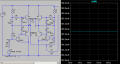
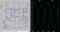
Ok in this circuit with your suggested values of 82 ohm resistors, when I use 470K feedback resistors, the current at A and B is between 20mA and 30mA measured in sim. and when I play with the input, I can't get the voltage difference (peak to peak) to exceed 1.3 on a 7.2V supply without distortion. Shouldn't I be able to get 4.5V somehow instead of 1.3 while keeping the quiescent current low? Is there a way around it without replacing the small 1N914's with fat 1N400x diodes?
 

Ian0

Joined Aug 7, 2020
13,228
Your simulation today has a high quiescent current because the forward voltage of your diodes is too high.
I think two 1A 1N4001 rectifiers will work but I do not have a model for it.

Many amplifiers have the two diodes replaced by a transistor with a variable resistor setting its voltage and the output transistors quiescent current.
Look up "Vbe multiplier".
@mike_canada :I told you in your last thread that your bias was too high, but you ignored me. The bias will be more predictable if you use three diodes and emitter resistors. The bias then can be calculated at Vdiode/(2R)
You can then calculate the minimum current in the bias chain, which will be Vout(max)/(Rload . Hfe(min)). You then needs a few milliamps more to go through the diodes. Hfe is the beta of your output transistors.
 

Thread Starter

mike_canada

Joined Feb 21, 2020
239
ok so my board does allow for emitter resistors. Right now those connections are shorted (so emitter resistors currently equal 0 ohms).

So what would the math be if I used 0.33 ohm emitter resistors?
 
Top