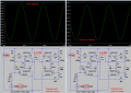
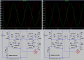
The TIP42 in bridged class ab amp is hot.

Audioguru again

Joined Oct 21, 2019
6,826
Emitter resistors are usually used in power amplifier circuits. Even your 2N2222 driver transistors should have them but will throw away some output voltage swing and throw away some output power.
Since the max undistorted output power of your amplifier circuit is so low then 0.33 ohms will do almost nothing. Higher resistance will use up some of your low output power.
 

Attachments

Thread Starter

mike_canada

Joined Feb 21, 2020
239
So the 2-diode idea that nearly everyone uses in their transistor class AB amps aren't good?

Maybe there's another diode as thin as a 1N914 I could try. 1N1418 seems to be too similar. Should I try to opt for thin ones with bigger voltage drops (if such diodes exist)
 

Thread Starter

mike_canada

Joined Feb 21, 2020
239
And I'm curious how do I calculate the total wattage when music plays?
do I take the voltage difference between the peaks at point A and B (outputs) in my bridged amplifier and for each voltage value multiply by sum of the largest current values from the power transistor emitters? then add the results together to get the total wattage?
 

Thread Starter

mike_canada

Joined Feb 21, 2020
239
The TIP41 and TIP42 have a 6A rating which is too high for your low amplifier power.
Try TIP31 and TIP32 power transistors for lower idle current.
I'm trying to not modify too many parts.
A little research on TIP41 and TIP31 tells me that TIP31 can handle less heat (40W) and less current (3A) than TIP41 (65W and 6A).

What if later down the road I want to change my supply to 14.4V and turn it into a car amplifier? Downgrading transistors then might fry them. At this rate, maybe I'll need to add resistors and capacitors in parallel in some parts of the circuit. But for now I'm sticking to one 7.2V battery.

I might have to suffer with slightly higher quiescent (between 60-100mA) current to get good voltage output across the board. At least this time I don't have it as crazy as 318mA
 

Jolly13

Joined Mar 25, 2018
44
Watts = Amps x Volts

Most just publish/discuss peak RMS not instantaneous. this site has a calculator https://www.allaboutcircuits.com/tools/rms-voltage-calculator/

Thought I saw a ltspice screen shot in a prior post Mike. Google it in ltspace ... on windows/ltspice usually alt right click a node to see wattage or power for a approximation based on design .

To some original question I would suggest Do not use visually inspection of wave if you can for audio.. since you have ltspace models .. do a fft and adjust biases by that output quality as you tweak PUSH/Pull bias. You will quickly realize your basic 2 diode may not fit your expectations.
...
If you really want to keep it this simple a 2 resisters one being a variable resister is going to be you best bet if the build is a one off and tune by hand as transistor worm up.

but will always be supply voltage dependent.


**NOTE** the .FOUR command is your friend here for audio circuits in ltspace.
 

Jolly13

Joined Mar 25, 2018
44
8 ohms x 14.4V = 25.92 watts.. if you peg it to a rails .. You will need heatsinks as you approach this .

But that's 1.8Amps at 8ohms

318mA may not be crazy in this circuit .. Model it in space or build it and run a FFT on it were you can measure distortion . PS worm up this circuit first.
 

Thread Starter

mike_canada

Joined Feb 21, 2020
239
Well, I think 318mA was the measurement when the transistors were too hot to the touch when I tried the circuit with 7.2V battery So I guess all those other waveforms and currents I mentioned don't matter then? Just the output resistance and source voltage I guess
 

Ian0

Joined Aug 7, 2020
13,228
So the 2-diode idea that nearly everyone uses in their transistor class AB amps aren't good?

Maybe there's another diode as thin as a 1N914 I could try. 1N1418 seems to be too similar. Should I try to opt for thin ones with bigger voltage drops (if such diodes exist)
Take another pair of TIP41/42 transistors and wire each as a diode (collector connected to base), and use them instead of the 1N4148s. Then they will be a good match to the output transistors, so you form a circuit similar to a current mirror. The idle current will then be the same as the drive current.
 

Jolly13

Joined Mar 25, 2018
44
Sorry is a hard thread to fallow .. 318mA will make TO220 transistors a bit hot yes (Heat Sinks are good ).. If I remember you indicate it was just one leg of the push pull , so balance may be off, but does it matter in this simple amp. Almost avoidable.

I would think 318ma is high, my point is if you rally want to try and drag race this thing .. look at total harmonic distortion .. probable way overkill but simple in your simulator and one more thing in you tool belt..

And of course you other measurement's matter you have learned a ton and will probable get a pretty fun little amp from it that you understand. . just do not overthink it .. biasing a AB is a balancing act with trade offs so no right answer ( that's the fun part), If you really pondering/sweating the bias problem .. simple ...make it and make it adjustable aka 1 variable resister on ground side of you network or better yet "listen to a prior poster" and ponder a VBE multiplier ( This is what AB audio amps want) .. a good listen( adjusting it) test may find a sweet spot with your circuit. If you going to simulate, pick a variable resister that can go from 0 quiescent current to maybe 384+ or so .. Power it up and listen tweak listen tweak ..

If you really want to hot rod this little thing minimizing harmonic distortion at like 1khz can be a ton of fun ..( you will hear under and over biasing ) so lowest current that sound great on you favorite song or ???.

Did seem like you were commenting for prior build was how load they are not. That's all about the speaker efficiencies at these voltage . Load Low voltage audio is hard with common speakers.

Have fun experiment SMOKE a couple of transistor. ( Heat sink's hint hint ) A lot of people have good comments in this thread re-read .. Remember no right answer just experience and 2 Cents( <- can be a heat sink) . Have fun and if it sound good woot .. else rinse and repeat.

Cheers ..

PS ----stick to the bigger Transistor for R&D work . if this is a one off who cares.
 

Thread Starter

mike_canada

Joined Feb 21, 2020
239
That's gonna cause me to redo my board which will cost more money. as I do not have space to replace a diode with a much bigger part. The nice news is the batteries I use are 7.2V 6800mAh and since I managed to make the standby current at the outputs from 318mA to about 60-100mA, thats a 3x improvement.

Also, when I run my amp, I run it with music for at least 45 consecutive minutes. The standby time is maybe 2 minutes (about the time I turn the amp power on to the time I start the music)

Have fun experiment SMOKE a couple of transistor. ( Heat sink's hint hint ) A lot of people have good comments in this thread re-read .. Remember no right answer just experience and 2 Cents( <- can be a heat sink) . Have fun and if it sound good woot .. else rinse and repeat.

Cheers ..
Funny thing is in my real tests, minus cranking up the volume, the sound was always good, but the problem I had were overheating transistors which is why I began this thread. I thought if I kept them overheating too long then I'd blow them up. Then again, maybe what saved me the most was the current and wattage handling capacity of the transistors.

Anyways, I did order heatsinks from Ebay. Yes Audioguru, you'll call it a cheeeep source of electronic trash. I know it isn't digikey. But I'm thinking once I get the heatsinks, I may add some thin wire and solder in between the nut, bolt and the transistor to hold the heatsink in place and for better connectivity. Sorry but thermal paste is on the expensive side. But I mean heat sinks are pieces of hard metal so I figure I could invent something.
 

Jolly13

Joined Mar 25, 2018
44
cool if it sounds good congrats .. if you have a circuit printed already .. min if any changes ... over heat sinking is the cure for many problems if you have space and resources. None of these transistor can do there stated amperage without thermal considerations ( aka heat sinks ) . Heat is what happens in this type of audio amps. Can you post the LTspice file for this board not a screen grab ?

NO reason for big changes as it is working .. Am i right assuming this is a one off .
 

Jolly13

Joined Mar 25, 2018
44
This is only like 20wats .. not a ton of thermal dissipation is needed , as you play just bolt a piece of mettal you have to the transistors.
High current at idle.. So you may just need to hand pick some diodes that get a little bit bigger spread than your initial test . May be some diodes you have has a higher turn on than the others as measured not speck sheet. may a 4001 .. spice will not help here ..
 

Ian0

Joined Aug 7, 2020
13,228
Also, when I run my amp, I run it with music for at least 45 consecutive minutes.
Then use class D. It will give you 33% longer battery life compared to the most efficient class B, and a bigger improvement versus class AB with a high bias current. I can tell from your analogue designs that sound quality isn't a priority.
 

Audioguru again

Joined Oct 21, 2019
6,826
And I'm curious how do I calculate the total wattage when music plays?
do I take the voltage difference between the peaks at point A and B (outputs) in my bridged amplifier and for each voltage value multiply by sum of the largest current values from the power transistor emitters? then add the results together to get the total wattage?
Music is played with various level peaks and sometimes with muted spaces in the sounds. Some of us think that the "average" output power is 1/10th the peak barely clipping power. But acid rock is played very loud all the time and only normal music has the variable levels.

Some amplifiers are made cheaply so that they play music for years but they smoke and burn when tested with a continuous high power output because they do not have enough cooling.
Modern amplifier ICs have temperature protection that mutes them when they become dangerously hot and their datasheets state how much you can reduce heatsink size when playing music.

The TIP31 has a max continuous power rating of 40W and the TIP41 has a continuous power rating of 65W only when their case is cooled with magic to keep it from heating more than 25 degrees C. Both are rated at 2W max without a heatsink when in free ambient air that is 25 degrees C. The datasheets have specs to select a heatsink.
 

Thread Starter

mike_canada

Joined Feb 21, 2020
239
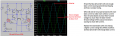
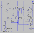
Ok I attached the latest spice file and the screen shot of the core circuit below. With this setup, I can almost achieve the same amplitude for output even if the supply voltage drops down to 5V. Idle current at 8V was measured to be about 100mA but I don't think my 7.2V battery will always run at 8V. Maybe at the beginning when its first charged. It's an NiMH toy car 6-cell battery. I can probably get away with 1/4 watt resistors but the 68 ohms I'll keep at 1W as those are already installed on-board.s.png
 

Attachments

Audioguru again

Joined Oct 21, 2019
6,826
The idle current is still very high because the low current diodes do not match the high current (6A) output transistors.
Did you try TIP31 and TIP32 (3A) output transistors instead?

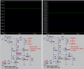
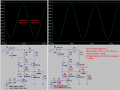
My simulation of your today's circuit shows the "b" amplifer has too much gain. Changing R5 from 39k to 56k fixed it.

The symmetry of the clipping does not change much when the 8V supply drops to 6V but of course the max output power drops to less than half.

This is using transistors with "simulation specs". When you build it, it will operate differently.
 

Attachments

Thread Starter

mike_canada

Joined Feb 21, 2020
239
Did you try TIP31 and TIP32 (3A) output transistors instead?
No and I don't have the funding for those now.


The idle current is still very high because the low current diodes do not match the high current (6A) output transistors.
What exactly do you mean by match? Does it mean the current specs for the diode are too low so almost no electricity flows through them? I'd like to know in an electrical sense because replacing the diodes with a more compatible model without thicker wiring would be better.
 
Top