The TIP42 in bridged class ab amp is hot.

Audioguru again

Joined Oct 21, 2019
6,826
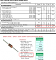
Look at the forward voltage of the diodes on their datasheet then look at the base-emitter voltage of the output transistors at the idle current you want.
The diodes have a higher forward voltage than the transistors which turns on the transistors too much causing a high idle current.

Your simple circuit produces low power but power amplifier IC have been used for many years to replace it. Higher power amplifiers built with separate transistors use a little transistor to drive them as a Sziklai pair and the base-emitter of the little transistors match the forward voltage of the little diodes like this:
 

Attachments

Jolly13

Joined Mar 25, 2018
44
Your spice file simulates with

At idle draws 200ma at power source.

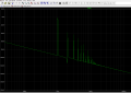
Total Harmonic Distortion: 0.010276%(0.010281%) at 1k input .. Not bad at all :)
firstFFT.png
Fourier components of V(out)
DC component:-0.00478076

Harmonic Frequency Fourier Normalized Phase Normalized
Number [Hz] Component Component [degree] Phase [deg]
1 1.000e+03 1.220e+01 1.000e+00 25.37° 0.00°
2 2.000e+03 1.022e-03 8.384e-05 -30.77° -56.13°
3 3.000e+03 7.195e-04 5.900e-05 73.82° 48.45°
4 4.000e+03 1.997e-05 1.638e-06 -25.61° -50.97°
5 5.000e+03 7.209e-05 5.911e-06 -23.35° -48.72°
6 6.000e+03 1.713e-05 1.404e-06 -8.92° -34.29°
7 7.000e+03 3.131e-05 2.568e-06 28.41° 3.04°
8 8.000e+03 1.601e-05 1.313e-06 7.19° -18.17°
9 9.000e+03 1.562e-05 1.281e-06 63.33° 37.96°
Total Harmonic Distortion: 0.010276%(0.010281%)
---------------------------------------------------------------
As usual .. your bench test show different ###.

?? SO You would like to
1. trying to decrease neutral heating on the Power transistor and not destroy audio and such.
2. try and avoid changing major components and interconnects .. ( We have a circuit board already and transistors ).
 

Attachments

Thread Starter

mike_canada

Joined Feb 21, 2020
239
fv.png

So after looking at everything here, does this mean the total voltage drop from all diodes connected to the power transistor bases must be at least the total VBE values from both transistors (which in this case is 4 1N914 diodes as opposed to 2)?
 

BobTPH

Joined Jun 5, 2013
11,619
Neither of those numbers applies because they are not measured at your operating currents. Vbe will likely be about 0.6V at the 20mA idle current you are aiming at.
 

Ian0

Joined Aug 7, 2020
13,230
Your spice file simulates with

At idle draws 200ma at power source.

Total Harmonic Distortion: 0.010276%(0.010281%) at 1k input .. Not bad at all :)
View attachment 277993
Fourier components of V(out)
DC component:-0.00478076

Harmonic Frequency Fourier Normalized Phase Normalized
Number [Hz] Component Component [degree] Phase [deg]
1 1.000e+03 1.220e+01 1.000e+00 25.37° 0.00°
2 2.000e+03 1.022e-03 8.384e-05 -30.77° -56.13°
3 3.000e+03 7.195e-04 5.900e-05 73.82° 48.45°
4 4.000e+03 1.997e-05 1.638e-06 -25.61° -50.97°
5 5.000e+03 7.209e-05 5.911e-06 -23.35° -48.72°
6 6.000e+03 1.713e-05 1.404e-06 -8.92° -34.29°
7 7.000e+03 3.131e-05 2.568e-06 28.41° 3.04°
8 8.000e+03 1.601e-05 1.313e-06 7.19° -18.17°
9 9.000e+03 1.562e-05 1.281e-06 63.33° 37.96°
Total Harmonic Distortion: 0.010276%(0.010281%)
---------------------------------------------------------------
As usual .. your bench test show different ###.

?? SO You would like to
1. trying to decrease neutral heating on the Power transistor and not destroy audio and such.
2. try and avoid changing major components and interconnects .. ( We have a circuit board already and transistors ).
-40dB is 1% not 0.01%, and 1% isn't hard to achieve at such a low power level. I bet it's nowhere near that good at 10dBv output.
 

Thread Starter

mike_canada

Joined Feb 21, 2020
239
Neither of those numbers applies because they are not measured at your operating currents. Vbe will likely be about 0.6V at the 20mA idle current you are aiming at.
What about for 100mA because Its tough to aim for 20mA while getting good volume output across a wide range of voltages. I might be lucky to go as low as 60mA.

How do I calculate the correct thin diodes then? Some datasheets don't give charts and like to give values based on their own current and/or voltage use.
 

Jolly13

Joined Mar 25, 2018
44
I was just playing with a germanium or Schottky .. in spice.. Does look like it pushes current way down and actually will act more like a A/B .. (using 1 BAS40-04HM) does drop idle current on powers trans to only 1ma or so .. seems to low .. but does not kill Total Harmonic Distortion: 1.961174%(1.988389%) in space model.
..
I can not stop thinking about the different ## you got when built and test it (300ma ).. just begs for some sort of adjustability at assembly time. Spice is only so good ...

The BAS40-04HM + 1n914 voltage Spread in the simulator varies from 1.03 - 1.114 V
The 1n914 + 1n914 voltage Spread in the simulator varies from 1.3 - 1.35V

Magic is between their some place appears.
 

Jolly13

Joined Mar 25, 2018
44
yup Ian .. the : 0.010276%(0.010281%) is not me it what ltpice drops to its logs .. sorry it a tool i.ve learned to not look at The %.

0.01 for this amp topology is good IMHA.
 

Ian0

Joined Aug 7, 2020
13,230
yup Ian .. the : 0.010276%(0.010281%) is not me it what ltpice drops to its logs .. sorry it a tool i.ve learned to not look at The %.

0.01 for this amp topology is good IMHA.
Rather too good.
-40dB for the 2nd harmonic means that THD already at 1% before you add in any of the higher harmonics.
 

BobTPH

Joined Jun 5, 2013
11,619
What about for 100mA because Its tough to aim for 20mA while getting good volume output across a wide range of voltages. I might be lucky to go as low as 60mA.

How do I calculate the correct thin diodes then? Some datasheets don't give charts and like to give values based on their own current and/or voltage use.
The idle current has nothing to do with the max output.
 

Audioguru again

Joined Oct 21, 2019
6,826
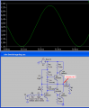
I also disagree that the distortion is very low because is visible (one peak of the sinewave is squashed) and it will be heard.
The second harmonic shows -40dB which is 1%. The 3rd and 4th harmonics are about 0.2% each.
Because the output is bridged then I think the even-numbered harmonic will almost cancel but will cause odd-numbered harmonics to increase.
 

Ian0

Joined Aug 7, 2020
13,230
I also disagree that the distortion is very low because is visible (one peak of the sinewave is squashed) and it will be heard.
The second harmonic shows -40dB which is 1%. The 3rd and 4th harmonics are about 0.2% each.
Because the output is bridged then I think the even-numbered harmonic will almost cancel but will cause odd-numbered harmonics to increase.
My estimation is that if there is visible distortion on a scope trace the THD is at least 5%
 

Thread Starter

mike_canada

Joined Feb 21, 2020
239
My estimation is that if there is visible distortion on a scope trace the THD is at least 5%
I've heard I'm pretty sure worse than 5% distortion from my amp when the battery level was dropping.

The idle current has nothing to do with the max output.
I take it as a factor in my whole design because to me it determines how long a battery can live. It seems what affects the output amplitude the most are the resistors connected to the base of the NPN transistors.
 

Audioguru again

Joined Oct 21, 2019
6,826
What about for 100mA because Its tough to aim for 20mA while getting good volume output across a wide range of voltages. I might be lucky to go as low as 60mA.

How do I calculate the correct thin diodes then? Some datasheets don't give charts and like to give values based on their own current and/or voltage use.
The idle current has nothing to do with good volume. Idle current of about 10mA to 30mA simply cancels crossover distortion.
Crossover distortion is very noticeable at low levels that frequently occurs in good music.
High idle current simply wastes battery power making heat.

When you build this simple circuit its performance will be very different than the simulation because the transistors and diodes have a wide range of specs. Then you will need to fiddle with many resistors to get it to work with the transistors you have.
 

Thread Starter

mike_canada

Joined Feb 21, 2020
239
I do have lots of resistors mostly of a couple of values from a previous large project I had to put on hold due to covid restrictions and now lack of cash.

I get it that I can't depend on 100% perfection from a sim as it is a computer. But I could get at least a rough idea of how well it turns out. Maybe I could increase resistor values by at least 1% or something as I don't want transistors frying in idle mode.

If I'm not mistaken, would an idle output current of 100mA with 8V supply make the TIP4x transistors stay cool to the touch? I mean my math leads me to 800mW and double that is 1.6W which is under 2W, then again someone mentioned some specs (particularly with wattage handling) were for marketing purposes?

I don't mind if I need some kind of heatsinks when loud music is playing. and I don't think my design will ever exceed 65W. I think my peak (according to the sim) is about 12W with music playing. It just would be nice if the parts are cool (or at least not oven-hot) when I have no music playing.
 

Jolly13

Joined Mar 25, 2018
44
YA I'm not a push/pull guy .. Did not see any clipping in my sims ,, am testing distortion off the voltage of speaker legs not across it. And have no sims of any other supply voltage but 8v .

My impression was that mike_canada was happy with the sound and concerned with heat and or battery draw. And does not want to spend much $ or scrap an existing circuit board or components.

Granted the current across the "Speaker" does not look greats , just start at DC offset at neutral from both halves :(.

But it sounds good enough( ive been told) .. any ideas on how to do a simple budge or or value change. Lower current and not kill audio.


This transistor current offset is what seems to be a low hanging fruit .
Wondering how to actual get both legs of first stage to act like a AB one legs is never getting close to tuning off.
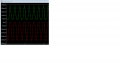
hotCurrent.png
 

Jolly13

Joined Mar 25, 2018
44
Hey mike_canada yes the r3 in you model is a feedback resister but is a current feed for your 2n2222 making it larger will pull both halves of the push pull toward neutral.. again a lot of feed back is good to kill distortion .. Try it on the sim and or on your board would be my hunch .. IF you have a potentiometer solder it in with some lead wires.. for testing in the range 50k to 300k or so ?
..
You never confirmed .. you have a pre built bord for this .. and you concerns are heat and current.
 

Thread Starter

mike_canada

Joined Feb 21, 2020
239
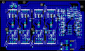
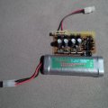
Yes and the blue thing is the PCB that's a bit zoomed out. Some traces look like they're touching but they're not. Almost every trace is 86mils wide (2.1mm) so the heat level on the board itself can be at minimum. The entire board consists of a low voltage detector, the stereo amp and the VU unit with the LEDs connected via ribbon cable. the little LED circuit is a simple SIP resistor bar with LED's attached to it. I have no issues with that particular little board.

The battery I use is included in the picture. 6800mAh 7.2V. And I'm not powering it in the state it's in right now until I change a few parts on it.
 

Attachments

Jolly13

Joined Mar 25, 2018
44
At least in spice 200-220 will reduce wasted current draw by 50% .. ( betting in circuit will about same ratios )

100k does give you a ~0 CenterPoint delta for voltage offset inSpace ..PROBABLE WHY IT WAS CHOSEN :) aka lets not kill your speaker with DC current. ps it is only 4mv or so .. way outside our window of error ,
 
Last edited:
Top