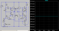
The TIP42 in bridged class ab amp is hot.

Thread Starter

mike_canada

Joined Feb 21, 2020
239
It takes about 13 seconds before the transistors are too hot to touch. Which to me suggests thermal runaway. Maybe the wattage I'm feeding into them is past the thresh hold for thermal runaway to begin but what is that thresh hold for TIP41/42? unless I'm not calculating wattage correctly?
 

Thread Starter

mike_canada

Joined Feb 21, 2020
239
Maybe I'm better off buying a 6 or 7V regulator, that way the parts won't overheat from an over-charged battery and on a fully charged battery I won't be burning much power
 

Thread Starter

mike_canada

Joined Feb 21, 2020
239
v.png

Sorry if I seem excited but I might end up having to go to the electronic store AGAIN tomorrow for parts because experimentation tells me that if my battery voltage exceeds 7.75V in my design, then I'm going past 2W of output on all power transistors. The battery itself is labelled for 7.2V but didn't someone say they could go as high as 8V (at least during charging if not after)?
 

MrChips

Joined Oct 2, 2009
35,018
You are going about this all wrong.

The output transistors are overheating because the quiescent current is too high. Reduce the base bias voltages.
 

Thread Starter

mike_canada

Joined Feb 21, 2020
239
Then if I did that I might get lower sound amplitude.
Is quiescent current in my circuit the current found at the power transistor emitters when its on and no audio is being driven into it?
Then again I may look at changing these resistors:

150 to 220 ohm
43K to 56K
24.2K to 27K

Measuring with those values gives me 1.96W at 8V input but is there another property in the transistor (tip41 and tip42) I need to be aware of or does heat officially start at 2W without a heatsink?
 

Audioguru again

Joined Oct 21, 2019
6,826
If two TIP41 are in series with two TIP42 and they draw 1.8ADC continuously from 7.2V then their total power is 1.8A x 7.2V= 12.96W. Then each transistor heats with 3.24W.

Your amplifier output transistors are suppost to be class-AB not class-A.
You showed them wrongly idling (no signal) at 200mA (almost class-A) instead of idling at 20mA or 30mA for class-AB.
Their peak momentary current was a little over 800mA pear pair.

Maybe you built the amplifier and are measuring the current with a meter designed to measure continuous current, not audio pulses from an audio amplifier.
 

Thread Starter

mike_canada

Joined Feb 21, 2020
239
How did you arrive at that conclusion or are you just making this up?
Less current means less power. then again maybe gain can compensate.

If two TIP41 are in series with two TIP42 and they draw 1.8ADC continuously from 7.2V then their total power is 1.8A x 7.2V= 12.96W. Then each transistor heats with 3.24W.
How did you calculate that my circuit was drawing 1.8A?

You showed them wrongly idling (no signal) at 200mA (almost class-A) instead of idling at 20mA or 30mA for class-AB.
Their peak momentary current was a little over 800mA pear pair.
Did you double the peak current value to calculate 1.8A?
Sometimes my real circuit is like that (between the time I turn the amp on and the time I start the music).

Maybe you built the amplifier and are measuring the current with a meter designed to measure continuous current, not audio pulses from an audio amplifier.
I used LTSpice.

So I take it that the best way to go about this whole thing is to take the peak current, multiply by 2 then multiply by voltage and subtract 2 to find out how many watts I'm over so I can figure out whether I need a heat sink or not?
 

Audioguru again

Joined Oct 21, 2019
6,826
The base-emitter conducting voltage of each complementary pair of the TIP transistors is supposed to match the conducting voltage of the pair of series 1N914 diodes. One pair of the TIP complementary base emitters are being turned on too much with a voltage that is too high from the pair of series diodes.
To fix it use diodes with a lower forward voltage. Try 1N4001 rectifier diodes.

Thermal runaway is caused by a high current heating the base-emitter of a transistor which causes its forward voltage to drop.
But the two series diodes also drop their forward voltage when heated. Then bond the diodes to the transistors to prevent thermal runaway.

Did you try using 1N4001 rectifier diodes?
 

Thread Starter

mike_canada

Joined Feb 21, 2020
239
I was considering them. I already made the PCB though and I'd probably wreck it if I tried shoving in heavier diodes.
Is my math right with determining peak power use?
or do I not multiply by 2?

When I set R6=R9=470 and R3=R2=100K and R5=39K, the max peak comes in around 370mA with an 8V supply from any power transistor emitter. Does this mean I'm using almost 3W or almost 6W of power?
 

Thread Starter

mike_canada

Joined Feb 21, 2020
239
1W is about the limit for a TO220 package without a heatsink
And all this time the datasheet stated 2W.
Well it looks like I have no choice but to use heatsinks, but since I'm on a budget, I found on hackaday.com that people used pennies and paperclips with solder as heatsinks and the paperclips with solder outperformed the pennies but I'm told they might be able to work for another watt of power but since my circuit might use 12W of power in the TIP transistors, I wonder if a whole bunch of paperclips (say about 15) bent then lined together to form a heavy blanket and then soldered together and onto the back of the transistors would work. I could connect the TIP41's together and then I could connect the TIP42's together. I wonder how good of a heatsink that would make.
 

Ian0

Joined Aug 7, 2020
13,227
And all this time the datasheet stated 2W.
Well it looks like I have no choice but to use heatsinks, but since I'm on a budget, I found on hackaday.com that people used pennies and paperclips with solder as heatsinks and the paperclips with solder outperformed the pennies but I'm told they might be able to work for another watt of power but since my circuit might use 12W of power in the TIP transistors, I wonder if a whole bunch of paperclips (say about 15) bent then lined together to form a heavy blanket and then soldered together and onto the back of the transistors would work. I could connect the TIP41's together and then I could connect the TIP42's together. I wonder how good of a heatsink that would make.
2W in free air, with 25°C ambient. If it is crowded together with other components, and the air around it is warmer than 25°C then it can’t manage 2W. Rule of thumb is 1W for a TO220 stood up on a pcb.

By the way, Class D amplifier are cheaper than heatsinks these days.
Forget about using anything steel (paper clips) because of poor thermal conductivity, and anything that isn’t perfectly flat (coins). Thermal conductivity of solder isn’t good either.
 

Martin_R

Joined Aug 28, 2019
137
I admire the perseverance of the TS. But as said many times, there's nothing in this design that is optimal, and with a high quiescent current the batteries are going to deplete rapidly. Class D would be the way forward for a low voltage battery powered amp.
On a side note, try shorting out one of the diodes on each amplifier side. Quiescent current will go down, but you may hear some crossover distortion. It may be unnoticeable as there is negative feedback into the first stage.
 

Ian0

Joined Aug 7, 2020
13,227
I admire the perseverance of the TS. But as said many times, there's nothing in this design that is optimal, and with a high quiescent current the batteries are going to deplete rapidly. Class D would be the way forward for a low voltage battery powered amp.
On a side note, try shorting out one of the diodes on each amplifier side. Quiescent current will go down, but you may hear some crossover distortion. It may be unnoticeable as there is negative feedback into the first stage.
A bit of crossover distortion would only add marginally to the approx 10% THD from the poor design.
 

MrChips

Joined Oct 2, 2009
35,018
TS continues to make erroneous statements and makes design decisions based on those false statements.

TS confuses DC power with AC power. DC power (quiescent power) through the output transistors is wasted power. TS needs to examine the AC power delivered to the load.

TS does not understand the difference between class A, class B and class AB amplifier.

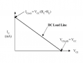
TS needs to study load line analysis and Q-point.
1664973056960.png

In class A amplifier, the Q-point is in the linear region of the load line.
In class B amplifier, the Q-point is in the low current region of the load line, i.e. towards the right in the diagram.
Unsurprisingly, class AB is a compromise between class A and class B.

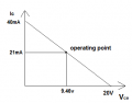
TS needs to learn how to set the Q-point and hence reduce wasted DC power and transistor over heating.

1664973093274.png

TS needs to understand that the emitter resistor is an inexpensive way of applying negative feedback and hence reduce crossover distortion.

I have offered to help TS meet his objectives on many occasions but have been completely ignored.
 

BobTPH

Joined Jun 5, 2013
11,616
You have probably already spent more on this than a class D amp board would cost, and you will never achieve equivalent audio quality and efficiency. Hopefully, the knowledge you have gained has been worth your effort.
 

MrChips

Joined Oct 2, 2009
35,018
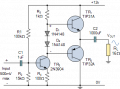
For the record, I just threw together a simple push-pull circuit similar to this one (but not exactly).


1664974316352.png

I used a PP3 9V battery and 2N3904 and 2N3906 output transistors (because that is what I have).

I also added emitter resistors and feedback to the base of the driver transistor.
(I trimmed the bias resistors so that the output is at half Vcc.)
The output sound level is too loud for normal listening while the transistors don't even get warm.
I had to add a volume control on the audio input.

My sound source is a simple LC crystal radio circuit with an MPF102 FET RF amp stage into a 1N34A detector.
 
Top