The TIP42 in bridged class ab amp is hot.

Thread Starter

mike_canada

Joined Feb 21, 2020
239
I'm looking at your output and you're using a 4 ohm resistor as the simulated speaker. I guess it means I'm on the right track to use the 7.2 ohm resistor as the load in my sim. But then again, why didn't you include an inductor in series with the 4 ohm resistor? And the coupling capacitor can add confusion with respect to my design because my output of the bridged amplifier uses no output capacitors.
 

Audioguru again

Joined Oct 21, 2019
6,826
The cheap but good amplifier module from ebay should have its PAM8306 amplifier IC made by Diodes Inc of USA, not a lousy Chinese copy. When it is set to the "class-D" mode then it barely heats and does not need a heatsink.
 

Audioguru again

Joined Oct 21, 2019
6,826
I'm looking at your output and you're using a 4 ohm resistor as the simulated speaker. I guess it means I'm on the right track to use the 7.2 ohm resistor as the load in my sim. But then again, why didn't you include an inductor in series with the 4 ohm resistor? And the coupling capacitor can add confusion with respect to my design because my output of the bridged amplifier uses no output capacitors.
My sim uses only one of the two bridged amplifiers, then to have the same output voltage swing and current swing as in the bridged amplifier, the load on my single amplifier has half the impedance of the load in the bridged amplifier.
Sometimes your speaker is 6 ohms, 7.2 ohms and 8 ohms.
 

Thread Starter

mike_canada

Joined Feb 21, 2020
239
Sometimes your speaker is 6 ohms, 7.2 ohms and 8 ohms.
Isn't that all the more reason to use an inductor (or inductor and resistor in series) as a speaker since the resistance value of an inductor varies with frequency? or are you saying that the speaker resistance changes value for some other reason other than a change of frequency?
 

Audioguru again

Joined Oct 21, 2019
6,826
The 200uH inductance of the speaker is so small that it has no effect below 1500Hz when it is a short piece of wire.
At 5kHz the impedance of the inductance is only 2.2 ohms.
 

Audioguru again

Joined Oct 21, 2019
6,826
My amplifier simulations are done at 1kHz where the small inductance of 200uH has no effect.
The datasheet for your 4" speaker says at 400Hz its impedance is 7.8 ohms.
 

Thread Starter

mike_canada

Joined Feb 21, 2020
239
So are you suggesting I should run tests with 1Khz input waveforms instead of 30Hz waveforms that I've been doing? I picked a lower frequency because I wanted the waveform to look nice across a wide range of frequencies.
 

Audioguru again

Joined Oct 21, 2019
6,826
Your little speaker can barely produce 30Hz. Most amplifier datasheets show specs at 1kHz.
The waveform with a smooth sinewave input should look the same at the output for all audio frequencies from 20Hz to 20kHz.

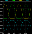
Your simple amplifier circuit shows the bottom of the waveform squashed a little which is distortion for each half of the bridged amplifier.
 

Thread Starter

mike_canada

Joined Feb 21, 2020
239
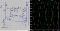
a.png

I did play with some values a bit (because sometimes stores don't have specific parts I'm looking for). And when I ran tests, the waveform is the same at 30Hz and at 1Khz. and this is with a 7.2 ohm resistor as a speaker. I still think simulating a speaker is more involved than using a simple resistor.
 

Audioguru again

Joined Oct 21, 2019
6,826
Your last simulation looks perfect because it wrongly assumes the transistors have perfect matching.
If you build it then the performance will probably be poor unless you buy many transistors and test and group similar ones, then fiddle with the resistors.
 

ericgibbs

Joined Jan 29, 2010
21,532
Hi Mike
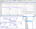
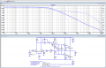
As a quick check, I have added this speaker model to the LTS Examples Audio amp.
E

BTW: Post your LTS asc file

EG57_ 83.png
 
Last edited:

Thread Starter

mike_canada

Joined Feb 21, 2020
239
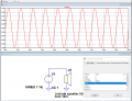
c.png

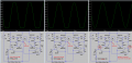
Ok the amp is also connected to my VU meter. I did change some part values and I think the biggest factor with temperature was R6 and R9. I tested batteries that were partly used and my junky voltmeter measured some of them to be at 6V so I tested with those then I did a test with 5 AA cells (7.5V) which is greater than the voltage I'd normally use (7.2V). Nice thing is the transistors were not hot despite having no heatsink, but they were warm. Then again, I made the input amplitude at the low end in the real tests. I begin to wonder if I still need heatsinks for when I crank up the volume because the current readings at a high volume (amplitude =.29V) means current exceeds 700mA at times. and even multiplying that by almost a dead battery (say 3V) would exceed the transistor heat rating without a heatsink (of 2W).

cu.png
 

Attachments

ericgibbs

Joined Jan 29, 2010
21,532
Hi Ian,
The circuit asc is from the LTS examples, check the Blue text explanation on the image, it is to check the Gain and Phase margins.
V4 is the reference source of the 1Vac test signal.
E

Updated Image, shows V(a)/V(b) plot
EG57_ 84.png
 

Attachments

Last edited:

Audioguru again

Joined Oct 21, 2019
6,826
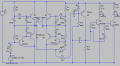
Mike, I do not have models of TIP transistors in my sim program.
The amplifier in your latest simulation is clipping like crazy because its input level is too high. When the level is reduced then the output is not symmetrical. I corrected the biasing.
I fixed it in the simulation but it will be different when you make it.
 

Attachments

Audioguru again

Joined Oct 21, 2019
6,826
Thanks Eric, but which of the many pages (that have no logical sequence) has the model of a TIP41?
I do not know which program (that I probably do not have) opens the model file and where to put it.
Your second link of a thread shows a list of model specs but no link to the file with the model.

Since the Simulation model does not have the wide range of specs that could be any transistor you buy, then my "similar" transistors in the sim program work fine when resistors are adjusted for it.
 

Thread Starter

mike_canada

Joined Feb 21, 2020
239
Is it normal for a TIP41 and TIP42 to get hot without heatsinks when 1.8W pass through it?

I just tested my circuit with a newly charged 7.2V NiMH battery and the transistors heated up again. Then again I think someone said fresh batteries have slightly higher than advertised voltages?
 
Top