Temperature sensor with LM393 Comparator and NTC Thermistor

dl324

Joined Mar 30, 2015
18,405
Whats the range of temperatures with your cct?
Can you set it at specific values? All I want is 30,40,50 and 70*C.
I intended to have a range of 0-100C, as in your original design. Because I used an LM3915, the indicators aren't evenly spaced.

This is what I calculated the displayed voltages to be (after tweaking the reference voltage to be a little lower):
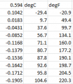
1724768783364.png

Since lower voltage means higher temperature, the display is "backwards"; LEDs turn off at higher temperatures. At ~100C, all LEDs are off. I used bar mode and the last two LEDs are off at room temperature. I made them all turn off by using my hot air tool. I could get the second one (corresponding to ~10C) to turn on by using some freeze spray on the transistor.
I think it will swing through an entire range with a set minimum and set maximum, and it will open its outputs for each 1/10'th between these set values. Right? The best you can do is to catch the closest to 40 or 50 and set that as my point. Is how I see it.
With an LM3914, you can get 10 evenly spaced temperature indications. You determine what they are by using an appropriate amplification and setting the reference voltage and RLO appropriately.
 

Thread Starter

q12x

Joined Sep 25, 2015
2,227
And can you limit it in the 30-70 range? If you can, you can get closer to the 40 and 50, you have more chances, more values to choose from. But the endings must be perfect on 30 and 70, or with very small tolerances.
Did you hunt for my shifting problem? when you raise up the temp collect the temp on paper from your electronic thermometer and when you let it cool also collect it. See if is a difference, if you have my shifting problem and how many *C apart they are.
 

dl324

Joined Mar 30, 2015
18,405
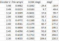
Here's my complete table:
1724771962957.png
I calculated the voltages for the internal voltage divider. I calculated the pre-amplified junction voltage based on the amplification of 5.7. I measured the junction voltage at room temperature (0.594). Calculated temperatures using that data.
But the endings must be perfect on 30 and 70, or with very small tolerances.
That's too difficult to do with LM3915. I'll try that with an LM3914 if I can find one.
Did you hunt for my shifting problem?
The video was too long and I didn't see what the problem you were trying to describe.
when you raise up the temp collect the temp on paper from your electronic thermometer and when you let it cool also collect it. See if is a difference, if you have my shifting problem and how many *C apart they are.
The time constant is too short for me to be able to take temperature measurements.
 

Thread Starter

q12x

Joined Sep 25, 2015
2,227
ok then.... its a good experiment what you did there. But is not helping the "precision cause" Im after.
I'll suggest to you to make my cct with LM393 digital comparator and see if you can get less shifting error between readings.
If you do, then your sensor is better than mine. If not or equal meaning 5*C difference, then doesnt mater what sensor we use.
It is very easy and fast to breadboard it. I recommend to use my setup, with 1R50W resistor at 5V for a few seconds to use as a heater over the sensor.
Most of the time I used only 1 comparator from the IC, and changed the volt-div resistors to hunt for the precision I wanted.
I also noted down all the values I took.
 

dl324

Joined Mar 30, 2015
18,405
C
But is not helping the "precision cause" Im after.
The transistor junction gives a linear indication of temperature. It's voltage changes by 2.2mV/°C. The HP thermometer I used for some previous experiments uses a 2N2222A as the sensor.
I'll suggest to you to make my cct with LM393 digital comparator and see if you can get less shifting error between readings.
If you do, then your sensor is better than mine.
I don't have any thermistors.

I made a video showing the circuit I breadboarded in operation. My HP bench meter is in the background, so you can pause and make conversions to indicated temperature if you're curious. Junction voltage at room temp (19C) is 0.602V.

I found that the transistor responds faster when I heat/cool the curved side of the package.
 

Thread Starter

q12x

Joined Sep 25, 2015
2,227
I don't have any thermistors.
This is my purchase record in 2022 for 100pcs 10valuesx10pcs each value and at 3$ price. I check it now on aliexpress and the prices are the same.
1724805112511.png
- But...because of my failure in precision specifically with these ones, I can not recommend them to you. All I can say they are cheap and in great quantity and variety is good enough, that was my logic when I took them. Like I said in my movie, they are good to give you a hint about the temperature youre measuring. But not at all precise because that shifting problem I demonstrated already.
Im actually searching right now for better thermistors.
- I bought these thermocouple instead. The rationament was, to have the same probe as my digital thermometer temperature sensor probe. To work in // with it. And theoretically, I should get the exact same response from my LM393 as my digital thermometer indicates, and hopefully without any shifting problem. Now Im very curious what it will be the result. If I still get a shifting problem, then.... its something wrong with my cct or something very clever in my digital thermometer that I have no clue yet.
- I really hope it resumes to the probe quality. What do you say? What it will be? Please share your opinion about this problem !
I consider these thermocouples superior in precision than my MF58 glass thermistors because I worked with both of them. I have great hope from these ones. We'll see...
1724806759060.png1724807173672.png
Thank you.
 
Last edited:

MrChips

Joined Oct 2, 2009
34,954
You are still making the same mistake.

There is nothing wrong with the thermistor. It is your expectation of the behaviour of the thermistor that is flawed.
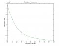
Now that I know that you are using NTC MF58 +/-5% 3950B, I have the data and will show you the resistance vs temperature curve.
 

Thread Starter

q12x

Joined Sep 25, 2015
2,227
You are still making the same mistake.
There is nothing wrong with the thermistor. It is your expectation of the behaviour of the thermistor that is flawed.
Now that I know that you are using NTC MF58 +/-5% 3950B, I have the data and will show you the resistance vs temperature curve.
- Its a possibility. But you don't help, you only correct me. You do make the difference between the 2, right? For example, mister @dl324 from USA actually build and tested in his side something, and that is what I consider helpful, and thats why is my friend. Also my UK friend Sarah, who is always trying something, that in the end is hinting me to the right direction.
- For NTC MF58, I provided the real name and its datasheet, in post #34.
 

MrChips

Joined Oct 2, 2009
34,954
- Its a possibility. But you don't help, you only correct me. You do make the difference between the 2, right? For example, mister @dl324 from USA actually build and tested in his side something, and that is what I consider helpful, and thats why is my friend. Also my UK friend Sarah, who is always trying something, that in the end is hinting me to the right direction.
- For NTC MF58, I provided the real name and its datasheet, in post #34.
I am correcting you because your basis of going from resistance to temperature is wrong.
I can help you get the correct temperature reading if you are willing to stop and listen for a change.
 

eetech00

Joined Jun 8, 2013
4,709
- Its a possibility. But you don't help, you only correct me.
It is not "a possibility", it is a reality. Everyone is trying to help you understand that the devices you have are a poor choice for what you want to do. The problem you are seeing is the non-linear characteristics of the NTC's you've purchased.
They are not designed to be linear, even with some compensation, it won't be linear thru its entire range. You'll need a different temperature sensing device, and/or method(micro-controller) if you want precision temperature measurements.
 

dl324

Joined Mar 30, 2015
18,405
And can you limit it in the 30-70 range? If you can, you can get closer to the 40 and 50, you have more chances, more values to choose from. But the endings must be perfect on 30 and 70, or with very small tolerances.
Can you describe the behavior you want? What do you want the LEDs to indicate between 30 and 70C. For example, for 40C, what do you want to happen below and above that temperature?

I'm planning to take a day off from working on my deck and might be inclined to breadboard something. I think I can put the transistor in a water bath to take measurements at certain temperatures.
But...because of my failure in precision specifically with these ones, I can not recommend them to you. All I can say they are cheap and in great quantity and variety is good enough, that was my logic when I took them.
I don't see myself using thermistors as temperature sensors when I already have thousands of transistors that can be used for that purpose. If someone gave me some, I might consider them, but from your experience, it seems like more bother than it's worth.

Whenever I've thought about doing anything with temperature, I always only considered transistor junctions because the voltage change is constant enough that professional temperature measuring equipment uses them.

I once considered making a circuit to control an incandescent lamp to keep my well from freezing, but I ended up just leaving a 100W bulb on whenever temperatures were going to be low enough to be a problem.

I also once considered making heaters for my chickens, but I don't have any chickens now...

A potential issue with components from AliExpress is that they could be rejects, counterfeits, or authentic parts.
 
Last edited:

MrChips

Joined Oct 2, 2009
34,954
I once considered making a circuit to control an incandescent lamp to keep my well from freezing, but I ended up just leaving a 100W bulb on whenever temperatures were going to be low enough to be a problem.

I also once considered making heaters for my chickens, but I don't have any chickens now...
Your chicks flew the coop because it got too hot?
 

Thread Starter

q12x

Joined Sep 25, 2015
2,227
I don't see myself using thermistors as temperature sensors when I already have thousands of transistors that can be used for that purpose. If someone gave me some, I might consider them, but from your experience, it seems like more bother than it's worth.
True enough. Then do my LM393 cct using your transistors as sensors. I can do it myself also.
See if you have BC548 because they are the usual test tr's for me. Or BD139 or BD681 - also usual test tr's.
You mentioned you tested with 2N2222, and I have 1 or 2 of them scrapped and not sure how stressed they are. I can do with it the test but... my usual test tr's are brand new.

Here is a list of some tr's I have: (BJT-NPN only)
Code:
               BJT-NPN small

MMBT3904  x100  40V   200mA 0.2W  SOT-23  SMD NPN  mark(1AM)    GPT_General Purpose Transistors   -SMD BOX-

BC548     x50   30V   100mA 0.5W  TO-92   TH  NPN Epitaxial Silicon Transistor   for Switching Applications      hFE=110-800

BC549     x??   30V   100mA 0.5W  TO-92   TH  NPN Epitaxial Silicon Transistor   for Switching Applications      hFE=110-800

BC238, BC337, BC639

MPSA42    x??   300V  500mA 1.5W  TO-92   TH  NPN HV-High Voltage Transistors

13001     x??   400V  300mA 0.75W TO-92   TH  NPN Epitaxial Silicon Transistor    for HiVoltage and HiSpeed Switching Applications        125ns(8MHz)

1or2 scrapped of these:

2N2369A, 2N5551, 2N2222, pN2222A, 2N930

C546B, C547, C517

BF199, BF173, BF255, BF254, BF167, BF214, BF215, BF200, BF198

              BJT-NPN POWER

BD135     x2    80V   1.5A  12.5W TO-126  TH  NPN  Medium Power Linear and Switching                                                    5us(200kHz)   hFE (40-250)@2V150mA

BD139     x90   80V   1.5A  12.5W TO-126  TH  NPN  Medium Power Linear and Switching                                                    5us(200kHz)   hFE (40-250)@2V150mA

BD237     x3    80V   2A    25W   TO-126  TH  NPN  Audio, power linear and switching applications                                       3us(333kHz)   hFE (40-xxx)@2V150mA

BD441     x10   80V   4A    36W   TO-126  TH  NPN  Amplifier and switching applications  (x8 pe shurub; x2 black heatsink)              3us(333kHz)   hFE (40-250)@1V500mA

BD681     x50   100V  4A    40W   TO-126  TH  NPN  Power Darlington Tr, Linear and switching industrial equipment                       1us(1MHz)     hFE(750-xxx)@3V1.5A

T1N4      x1    400V  1A    30W   TO-126  TH  NPN  Thyristor (facut in Romania)                                                         40us(25kHz)   hFE xxx

K D1691   x3    60V   5A    20W           TH  NPN  DC-DC converter, driver solenoid or motor                                            1us(1MHz)     hFE(K200-400)@1V2A  (found as 2SD1691)
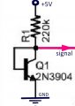
And this was your setup for your Tr as a termic sensor, from your last cct provided.
Did you changed anything until then or is the same now?
Screenshot_5.jpg
Did you use this as a volt-div? Or you put that 220k just as a protection and small current source?
- - -
Very well then, I started the experiment with a BD139 as my sensor, because of the big flat copper thermic dissipation on it's back.
 
Last edited:
Top