 Facebook
 Google
 GitHub
 Linkedin
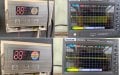
My Sanken Solar Water Heater Controller is faulty, so I am trying to design a new, improved controller using Arduino, ESP32, or Raspberry Pi. However, I need help understanding how the sensor transmits two different types of data — water level (indicated at 25%, 50%, 75%, and 100%) and temperature (in the 0–100 °C integer range) — using only two wires (i.e., a 2-core cable).
I have already tested the sensor using my oscilloscope to analyze the waveform. The sensor outputs a square wave with a pulse count of 25–28 at a temperature of 25 °C. The peak-to-peak voltage (Vpp) varies with water level: Vpp = 8 V at 0% and Vpp = 3.92 V at 100%. Unfortunately, I cannot get valid readings at 50% and 75% due to a fault, but I am confident that the 0% and 100% readings are accurate.
Here are the sensor: https://www.google.com/url?sa=i&url...ved=0CBQQjRxqFwoTCNDK882zno0DFQAAAAAdAAAAABBU
Attachments
-
 207.8 KB Views: 6


