 Facebook
 Google
 GitHub
 Linkedin
Hi
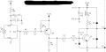
can you please explain why the in electrolytic caps are in series. (C6 and C3)
and what is the purpose of D4, i know d3 is used to protect against incorrect voltage input.
and what is the purpose of c4
Thanks in advance
Tom
can you please explain why the in electrolytic caps are in series. (C6 and C3)
and what is the purpose of D4, i know d3 is used to protect against incorrect voltage input.
and what is the purpose of c4
Thanks in advance
Tom
Attachments
-
 61.4 KB Views: 39


