Temperature sensor with LM393 Comparator and NTC Thermistor

Thread Starter

q12x

Joined Sep 25, 2015
2,227
Use an LM35 ->> Opamp ->>to an LM3914.
I had some time and breadboarded this circuit
Thank you !
I did find a similar circuit but using that LM35 termistor. I believe the opamp in this cct is having the role of amplifying the signal, while the LM3914 is doing the comparator thing Im doing here with my LM393.
- I made a movie about the "shifting" problem that no one here is aware about, you only guess what it might be, even after I explain it very clearly, in one of my beginning posts. Now Im editing it and in 1h or so I will publish to YT. Its good if you will watch it to be aware of the actual problem Im facing and others like me who have these components.
 

dl324

Joined Mar 30, 2015
18,405
I believe the opamp in this cct is having the role of amplifying the signal, while the LM3914 is doing the comparator thing Im doing here with my LM393.
That's right. The junction was at 0.6V at room temp (18C). I heated it up until it dropped to 0.4V and I set that voltage for the lowest LED (#1) after amplification.
 

Ian0

Joined Aug 7, 2020
13,158
Unless you already have the temperature sensor, using a transistor would be more convenient. You just have to scale the voltage appropriately.
The LM35 or a curve-matched thermistor will be the most "convenient". No other solution allows all the resistor values to be calculated beforehand. Using a transistor or diode would require the circuit to be calibrated after building.
 

dl324

Joined Mar 30, 2015
18,405
The LM35 or a curve-matched thermistor will be the most "convenient". No other solution allows all the resistor values to be calculated beforehand. Using a transistor or diode would require the circuit to be calibrated after building.
@q12x prefers circuit suggestions that use parts he already has.
 

dl324

Joined Mar 30, 2015
18,405
Precisely. In Post #34 he posts a link to a datasheet which says "4. High precision resistance and B value" in other words, a curve-matched thermistor.
I'm pretty sure he has transistors... I posted a circuit I suggested and verified that it works. It will be much easier to breadboard than the thermistor circuit he attempted.
 

Thread Starter

q12x

Joined Sep 25, 2015
2,227
- Im in both worlds. I like to use what I have, like @dl324 said because he knows me for a long time. But I also want in the same time what is the best solution too, so new components are welcomed. That's why I like this open forum discussions, to collect the most info that I can. Even if I cant do it "right now" I will do it sometime later if pops out as interesting enough.

Precisely. In Post #34 he posts a link to a datasheet which says "4. High precision resistance and B value" in other words, a curve-matched thermistor.
That post is when I realized the actual name of this component and I got the bright idea to search for its datasheet and gloriously, I find it. And I did thought too, mostly guessed, that it should be like you say, "a curve-matched thermistor". But for me its a new thing thats why Im a bit uncertain in some points.
- What I really hate about these thermistors I have here, is that they are not accurate - AT ALL- ! As they should be, as you mister @Ian0 are suggesting they should be. This is the very first time when Im actually dealing with a thermistor in my circuits. I know about their existence but actually putting your hands on them and building stuff, gets you into errors and bugs like the ones Im facing. I really hope its just a silly thing that somebody can correct it quickly and get over it. Haha. I wish. Because that shifting Im mentioning from the very beginning and now Im editing the movie about it and is hard and boring and slow to do it. I will finish it, but not as fast as I thought. Its a bit of hard work involved in editing movies.
 

Ian0

Joined Aug 7, 2020
13,158
I use this one:
https://uk.rs-online.com/web/p/thermistor-ics/0151221?gb=s
The datasheet on the link is dreadful - it says it is a "curve matched thermistor" but doesn't state the curve to which it is matched: The "B" parameter is not mentioned.
After some ridicule - asking RS how it could possibly be "curve matched" without stating which curve, they gave me a proper datasheet.
I use a microcrocontroller and a look-up table to get the temperature, and the parts are indeed interchangeable. Replacing the thermistor with another one of the same type gives the same temperature reading.
 

Thread Starter

q12x

Joined Sep 25, 2015
2,227
The "B" parameter is not mentioned.
What is that "B" parameter after all? I personally assumed it is something but I got no affirmative for it.
Also, did you seen in my movie what Im dealing with, with my "shifting problem" ? Is that what should a normal sensor behave? What do I miss?
Please confirm(or infirm) if what Im having is a good reliable precision NTC.
I use this one:
So you are suggesting to use one that you use. I already have a ton of those glass ones for a large range of values.
But I also have one of yours, that I scrapped from a very cheap human body thermometer. the problem is that I have only a single one. Not in big quantities and ranges like the glass ones. And I just measure it, it has 41k at 30*C ambient temp in my room since its still summer and we were blessed with wave after wave of heat for 3 months.
 
Last edited:

Thread Starter

q12x

Joined Sep 25, 2015
2,227
Hi q12,
A quick Google explains the 'B' parameter.
E
https://www.ametherm.com/thermistor/ntc-thermistor-beta
Ok thanks, I read it now. It did not cross my mind to search for it - ha. So that B or beta is the curve shortcut name after all. And that curve looks very similar to the Steinhart–Hart_equation using it's 3 variables ABC. It might be the same thing but with different naming... but I get it now, its a curve of RT (Resistance-Temperature) response and prediction.
 

Ian0

Joined Aug 7, 2020
13,158
What is that "B" parameter after all? I personally assumed it is something but I got no affirmative for it.
Also, did you seen in my movie what Im dealing with, with my "shifting problem" ? Is that what should a normal sensor behave? What do I miss?
Please confirm(or infirm) if what Im having is a good reliable precision NTC.

So you are suggesting to use one that you use. I already have a ton of those glass ones for a large range of values.
But I also have one of yours, that I scrapped from a very cheap human body thermometer. the problem is that I have only a single one. Not in big quantities and ranges like the glass ones. And I just measure it, it has 41k at 30*C ambient temp in my room since its still summer and we were blessed with wave after wave of heat for 3 months.
All NTC thermistors should work, and curve-matched types should need no calibration.
 

Thread Starter

q12x

Joined Sep 25, 2015
2,227
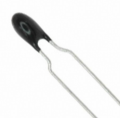
I just test it with my scrapped single NTC droplet no-name like the one @Ian0 showed me his model that is having.
1724662475302.png
And I tested over the setup I have it there. I only change the 1k into 39k SMD since it was the closed to the 41k of the NTC to make a VCC*1/2 V-div. ANd it worked, but for other voltages than before, obviously, and most interesting that this one too is having a shifting too. Not as great as 5 or 10*C as my glass ones, but 1 or 2*C.
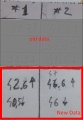
Here is the new tested data:
Screenshot_3.jpg
At #1 we see 2*C shift and for #2 about 1*C shift. Way more precise these ones. But it might be because this one is 40k volt div, while the other one was 1k volt div ? Hmmmmmm, I wonder....
 
Last edited:

Thread Starter

q12x

Joined Sep 25, 2015
2,227
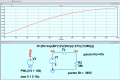
What is the Beta, Ro and Series resistor value for your project.?
From the aliexpress seller : B=3950 and I think it means this beta graph, but I cant pinpoint that number anywhere.
NTC_MF58 Thermal Resistor (Thermistor)_item.jpg
In the movie I used 1k NTC with a 1k smd resistor to form a VCC*1/2 V-div for the sensor circuit.
 
Top