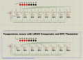
Temperature sensor with LM393 Comparator and NTC Thermistor

Alec_t

Joined Sep 17, 2013
15,130
the voltage is drifting
Probably because everything, importantly the thermistor, has a thermal time constant and can't respond instantly to a temperature change.
If your supply voltage drifts (have you confirmed it doesn't?) then so will the reference voltage.
 

MisterBill2

Joined Jan 23, 2018
27,726
In the industrial systems that I have designed the only varieties of temperature sensors used were either thermo-couple types, or 100 ohm RTD types, except for one system that used an ANALOG DEVICES semiconductor sensor.
That was because of the requirements for accuracy, stability, and interchangeability.

The only information we have about the potential application is that the TS is experimenting. And in that area, certainly there is learning about the accuracy and stability of thermistor sensors happening.
 

schmitt trigger

Joined Jul 12, 2010
2,123
IN ADDITION, the fairly large current flowing in the thermistor will certainly cause self heating. No way around that, either.
Exactly! Self heating is an issue.
One way I have found around it, but it it becomes a more complicated solution unless an uP is used, is to*only power the thermistor* for a few milliseconds while the temperature is read, and remove power for the remainder. It only requires an output pin and an ADC input pin in a micro.
 
Last edited:

dl324

Joined Mar 30, 2015
18,403
not like this crap lm393 with only half of the normal output, what a bad joke it is
AFAIK, all of the comparators from that era were open collector; and it was never much of an issue. If you want a push-pull output, put a CMOS inverter on the output as I did with the PWM circuit you were using to test MOSFETs.

Some newer CMOS comparators have push-pull outputs, but they're also more expensive and sometimes have a smaller operating voltage range.

Don't bad mouth old designs. They were considered good/great when they were first introduced and are still useful if you understand their limitations. It's a poor craftsman who blames his tools...
 

Thread Starter

q12x

Joined Sep 25, 2015
2,227
From what I understand, there is no such precise thermo sensor (whatever its type from the 4 enumerated in the beginning).
So
One end of the 1K resistor should connect to 5 volts not ground.
And all the LEDs are shown reversed.
In the OP, I used a general purpose comparator and also I used it's normal logic too.
That's why it looked 'messed up' from LM393 perspective.
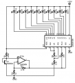
Here, I Corrected the cct specifically for LM393 comparator. I start to learn it's limitations now.
1724373442378.png
As a fun note, even the creators of the Proteus simulator were confused or annoyed by this one, so they left it as a bugged component, hahaha.
 

AnalogKid

Joined Aug 1, 2013
12,174
Here, I Corrected the cct specifically for LM393 comparator. I start to learn it's limitations now.
View attachment 329862
Still incorrect.

In the lower schematic you reversed the + and - inputs to the comparators. This is incorrect. The upper schematic is correct in this area. It's only problems are the 1K resistor GND connection and the reversed LEDs.

ak
 
Last edited:

AnalogKid

Joined Aug 1, 2013
12,174
From what I understand, there is no such precise thermo sensor
Incorrect. An NTC thermistor is an excellent sensor; some are accurate to within 0.1 degree C. BUT, you have to a part that is the correct one for your circuit, and a circuit that is the correct one for your part. As above, self-heating and radiative cooling are things that have to be accounted for.

ak
 

MisterBill2

Joined Jan 23, 2018
27,726
The original application/motivation for comparator outputs being NPN-open collector was probably to allow very easy "wired OR operation, in addition to allowing them to have the output voltage different from the internals supply voltage.
 

Thread Starter

q12x

Joined Sep 25, 2015
2,227
- What is the formula for making a more precise/accurate thermometer reading?
What it involves? Everything points to programming only? No other way?
- Does anyone know other better electronic thermometer circuit diagrams?
- For example, right now I get a range, between 53 and 47 where the sensor shifts when temp rises or falls. I kind of calibrated around 50 I want to say but Im doing it totally by the ear. I have a VERY imprecise thermometer reading right now. Which is fine if you dont mind for accuracy, but I do mind.
 
Last edited:

Ian0

Joined Aug 7, 2020
13,158
- What is the formula for making a more precise/accurate thermometer reading?
It is the Steinhart-Hart equattion.
https://en.wikipedia.org/wiki/Steinhart–Hart_equation
I have a VERY imprecise thermometer reading right now.
Yes - in only reads to the nearest 10 degrees because there are only 8 LEDs.
I use the Steinhart-Hart equation to produce a lookup table, which I use to obtain the temperature from the output of an A/D converter.
You can use resistors to linearise the output of the thermistor, but it only works well over a small range.
You can buy curve-matched thermistors.
https://docs.rs-online.com/143b/A700000007790677.pdf
 

dl324

Joined Mar 30, 2015
18,403
Does anyone know other better electronic thermometer circuit diagrams?
Have you considered using a diode connected transistor and an LM3914?

Vbe increases around 2mV/°C. The "diode" is operated at a low current (<100uA). You could use an amplifier to spread out the voltage range.

In the old days a 2N2222A was often used, but I saw Linear Tech app note that said they calibrated their chips for 2N3904 and 2N3906. I thought a metal package would give better (faster) heat transfer.
 

Thread Starter

q12x

Joined Sep 25, 2015
2,227
It is the Steinhart-Hart equattion.
I read your page and those formulas needs 3 values A,B,C that I should obtain experimentally. They are not specifying how to obtain them experimentally. So that page with all its formulas in it, falls to the drain, since it is an incomplete explanation.
Here, Im quoting:
" To find the coefficients of Steinhart–Hart, we need to know at-least three operating points. For this, we use three values of resistance data for three known temperatures. "
" The equation was developed through trial-and-error testing of numerous equations, and selected due to its simple form and good fit. However, in its original form, the Steinhart–Hart equation is not sufficiently accurate for modern scientific measurements. "

-From that page I find a link to this other page that is indeed giving all the values for ABC. But it is letting you guess what category you want. I guess, that my thermistors ABC are in the -F- (R/T curve). Oh wait.. might be -G-, hooold on, hold on, I decided it might be -W-. This is how you do science these days - hahaha. And even if I had the correct ABC, I still have to deal with those formulas. MF ! hahaha. I think its a joke and I cant take it seriously. It very well be only a part of the answer, but the other part is written on paper, not on internet and hold as a dear secret only by the few known. If people know these values are simply experimental, by the ear and by the smell, and not 'real solid math', they will shoot us. Hahaha. Its how I see it. Anyway...
- I also looked on my seller page on Aliexpress
NTC_MF58 Thermal Resistor (Thermistor)_item.jpg
and I found the name of these thermistors is MF58. I also google for it and I found this datasheet .
What is that B value (3950) mentioned in their title? It is related to this Steinhart–Hart formula? If yes why not giving all the numbers for A,B,C ? Or that B might be something else? But what ?
- I want to believe my thermistors marketing data, that can be used as 1% accuracy. Maybe the cct Im using is skewing the results?
Have you considered using a diode connected transistor and an LM3914?
- I did. It was the very first articles I find when I start searching for my thermistors. They used 1N4148 diode. But my UK friend told me in particular not to use them. So I concentrated on my thermistors I already have and left that aside.
If you have a circuit that you know for sure is working and not experimental on your table, or at least from a good source that you trust, do give it here to make it and to expect the same values in paralel with you there. We never had any same paralel results or data (as an observation). But we will, someday. Haha.
 

dl324

Joined Mar 30, 2015
18,403
I did. It was the very first articles I find when I start searching for my thermistors. They used 1N4148 diode. But my UK friend told me in particular not to use them.
If they were using 1N4148, they didn't know what they were doing.
If you have a circuit that you know for sure is working and not experimental on your table
I've never had the need, or desire. It'll probably be weeks before I'll have time to work on circuits. Still working on my deck and I need to finish it before the rainy season starts.
 

Thread Starter

q12x

Joined Sep 25, 2015
2,227
I've never had the need, or desire. It'll probably be weeks before I'll have time to work on circuits. Still working on my deck and I need to finish it before the rainy season starts.
So you have no idea how to improve this sensor reading.
Fine then.
I'll build my crappy very imprecise one then. I already start to draft it for a few days, but I paused it in the hope better version/idea will come. Eh well, I tried.
1724548227138.png
 

Ian0

Joined Aug 7, 2020
13,158
I read your page and those formulas needs 3 values A,B,C that I should obtain experimentally. They are not specifying how to obtain them experimentally. So that page with all its formulas in it, falls to the drain, since it is an incomplete explanation.
Here, Im quoting:
" To find the coefficients of Steinhart–Hart, we need to know at-least three operating points. For this, we use three values of resistance data for three known temperatures. "
" The equation was developed through trial-and-error testing of numerous equations, and selected due to its simple form and good fit. However, in its original form, the Steinhart–Hart equation is not sufficiently accurate for modern scientific measurements. "

-From that page I find a link to this other page that is indeed giving all the values for ABC. But it is letting you guess what category you want. I guess, that my thermistors ABC are in the -F- (R/T curve). Oh wait.. might be -G-, hooold on, hold on, I decided it might be -W-. This is how you do science these days - hahaha. And even if I had the correct ABC, I still have to deal with those formulas. MF ! hahaha. I think its a joke and I cant take it seriously. It very well be only a part of the answer, but the other part is written on paper, not on internet and hold as a dear secret only by the few known. If people know these values are simply experimental, by the ear and by the smell, and not 'real solid math', they will shoot us. Hahaha. Its how I see it. Anyway...
- I also looked on my seller page on Aliexpress
View attachment 330033
and I found the name of these thermistors is MF58. I also google for it and I found this datasheet .
What is that B value (3950) mentioned in their title? It is related to this Steinhart–Hart formula? If yes why not giving all the numbers for A,B,C ? Or that B might be something else? But what ?
- I want to believe my thermistors marketing data, that can be used as 1% accuracy. Maybe the cct Im using is skewing the results?

- I did. It was the very first articles I find when I start searching for my thermistors. They used 1N4148 diode. But my UK friend told me in particular not to use them. So I concentrated on my thermistors I already have and left that aside.
If you have a circuit that you know for sure is working and not experimental on your table, or at least from a good source that you trust, do give it here to make it and to expect the same values in paralel with you there. We never had any same paralel results or data (as an observation). But we will, someday. Haha.
I read your page and those formulas needs 3 values A,B,C that I should obtain experimentally. They are not specifying how to obtain them experimentally. So that page with all its formulas in it, falls to the drain, since it is an incomplete explanation.
Here, Im quoting:
" To find the coefficients of Steinhart–Hart, we need to know at-least three operating points. For this, we use three values of resistance data for three known temperatures. "
" The equation was developed through trial-and-error testing of numerous equations, and selected due to its simple form and good fit. However, in its original form, the Steinhart–Hart equation is not sufficiently accurate for modern scientific measurements. "

-From that page I find a link to this other page that is indeed giving all the values for ABC. But it is letting you guess what category you want. I guess, that my thermistors ABC are in the -F- (R/T curve). Oh wait.. might be -G-, hooold on, hold on, I decided it might be -W-. This is how you do science these days - hahaha. And even if I had the correct ABC, I still have to deal with those formulas. MF ! hahaha. I think its a joke and I cant take it seriously. It very well be only a part of the answer, but the other part is written on paper, not on internet and hold as a dear secret only by the few known. If people know these values are simply experimental, by the ear and by the smell, and not 'real solid math', they will shoot us. Hahaha. Its how I see it. Anyway...
- I also looked on my seller page on Aliexpress
View attachment 330033
and I found the name of these thermistors is MF58. I also google for it and I found this datasheet .
What is that B value (3950) mentioned in their title? It is related to this Steinhart–Hart formula? If yes why not giving all the numbers for A,B,C ? Or that B might be something else? But what ?
- I want to believe my thermistors marketing data, that can be used as 1% accuracy. Maybe the cct Im using is skewing the results?

- I did. It was the very first articles I find when I start searching for my thermistors. They used 1N4148 diode. But my UK friend told me in particular not to use them. So I concentrated on my thermistors I already have and left that aside.
If you have a circuit that you know for sure is working and not experimental on your table, or at least from a good source that you trust, do give it here to make it and to expect the same values in paralel with you there. We never had any same paralel results or data (as an observation). But we will, someday. Haha.
For your application which reads to the nearest 10 degrees, the B-parameter equation is going to be perfectly adequate.
The B-parameter equation and the way that the Steinhart-Hart equation is derived from it is on the Steinhart-Hart wikipedia page https://en.wikipedia.org/wiki/Steinhart–Hart_equation probably further down than you bothered to read.

This online calculator can work out the coefficients for you from measured values.
 

dl324

Joined Mar 30, 2015
18,403
If you have a circuit that you know for sure is working and not experimental on your table, or at least from a good source that you trust, do give it here to make it and to expect the same values in paralel with you there. We never had any same paralel results or data (as an observation). But we will, someday.
I had some time and breadboarded this circuit:
1724611458465.png
I couldn't find any LM3914, so I used LM3915.

I used my hot air tool on the transistor and observed the voltage changing with temperature. I heated the transistor enough to go off the scale (lowest voltage determined by R6). Since LM3915 isn't linear, I didn't bother to try to calculate actual temperatures.
 
Top