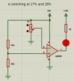
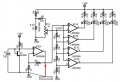
Temperature sensor with LM393 Comparator and NTC Thermistor

dl324

Joined Mar 30, 2015
18,405
I did a test using the 30-60C thermometer with the resistor heating circuit. The two transistors I used had a 1mV difference at 0C and I didn't bother making corrections to my temperature chart. I also changed the gain to 10 for both opamps. The second one was closer to 10.00, but I didn't bother making that correction. I used the data for the transistor with the lower temperature for all settings.

At first I set the heater to 30, 40, 50, then 60C. Later, I just set the heater to go slightly above 60 and monitored the voltage that each LED turned on. Then I monitored voltages as the resistor cooled (I sped it up by holding it in my fingers). I also increased the heating current to 200mA which seemed to make the overshoot problem come back.

Except for when a LED was about to turn on or off, the LEDs were either steady on or off. I don't have decoupling caps on the thermometer circuit.

I haven't converted the voltages that the LEDs switched to actual temperatures, but they were close to the set points.

Using the 10k resistors in the voltage divider for the thermometer circuit made it easy to change the trip voltages from a gain of 4.7 to 10. Just change the voltage on the wiper for the lowest temperature and change the 100k pot to set the highest temperature. The other two trip points scaled appropriately.

My breadboards and heater:
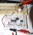
LM339Thermometer30-60withHeater.jpg
heatingResistor.jpg
 
Last edited:

Thread Starter

q12x

Joined Sep 25, 2015
2,227
so here is my problem.
WIth your cct, the LEDs are not turning off. If Im changing the POT to the limit between on and off, they remain on.
I noticed that when I turn the pot Up, Led A turn on Led B remains off, then I turn the POT some more then LED B turns On.
Next, when I turn the POT Down, Led B turns off but led A remains ON and when I turn the POT some more Led A turn OFF.
So its this gap. And this is one problem.
I replaced all those 10k in series with a single POT_2 to the (-) input to one comparator. Yes, now I have 2 POTs on the same line but only for a single compar.
And I got this result:
LedA off 32.8*C 3.06V
LedA on 43.1*C 3.02V
another test:
LedA off 50.1*C 2.90V
LedA on 42.2*C 2.94V
This is telling me something very weird is happening in my comparators. They work, but with very great delay, when connected to the sensor. He works fine when I put a single volt-div and a POT on its inputs! Its only when I connect a sensor to it, is misbehaving in a rainbow of errors. I believe, as you can see the last data, it is not having too much voltage difference. Also the first POT cct it might add some strange delay between switching LED A and LED B. Orrrrr the POT 1 cct is just fine, and this delay comes from inside the comparator for some reason. Although in the testing cct, behaves fine. This is VERY strange !!!
- I am amazed how your cct is working "correctly" as you so sure declare, switching its LEDs perfectly from 10 to 10*C and not having any kind of shifting problem like I have from the very beginning.
Testing cct. Data is for simulator only.
1724978300326.png
 
Last edited:

dl324

Joined Mar 30, 2015
18,405
WIth your cct, the LEDs are not turning off. If Im changing the POT to the limit between on and off, they remain on.
I noticed that when I turn the pot Up, Led A turn on Led B remains off, then I turn the POT some more then LED B turns On.
Next, when I turn the POT Down, Led B turns off but led A remains ON and when I turn the POT some more Led A turn OFF.
So its this gap. And this is one problem.
What voltage corresponds to the amplified sensor voltage sensor output for 30C and 60C? You set the voltage at the top of the voltage divider to the voltage that corresponds to 30C. Then you adjust the pot in series with the 220k resistor to set the voltage on the bottom comparator that corresponds to 60C.

I didn't have to use any decoupling capacitors on that circuit, but you should put 0.1uF across the power pins of all chips.
 

Thread Starter

q12x

Joined Sep 25, 2015
2,227
What voltage corresponds to the amplified sensor voltage sensor output for 30C and 60C?
"And I got this result:
LedA off 32.8*C 3.06V
LedA on 43.1*C 3.02V
another test:
LedA off 50.1*C 2.90V
LedA on 42.2*C 2.94V
"
In this last test I only checked if its switching correctly at a set temperature or set Voltage. Without the shifting problem.
I didnt care if its 30 or 60*C.
---
I took out the IC and mounted on another breadboard and made another health test just to be sure I dindnt f*itup in all this time.
And is switching very firmly as expected. So nothing is wrong with the IC.
Although... in my simulator and in reality, for 100k POT I got a deviation in POT travel lower switching event. Meaning, the POT was about 20% in reality when it was switching, not at it's 50% in the middle as it should be. Let's say is my very old 100k and very used in tests (also very scrapped). But it was switching firmly not with a gap as in the simulator (which is heavily bugged btw for this particular IC). But for VD_10k and POT_1k in reality I got a perfect middle 50% POT switch event.
For a Very fine turning from the POT, I could see the LED dimming like 50% and then turning off. I Could see it at 30% for a fraction of a second, but the tuning was extremely fine from the POT. Normally, the switching appears firm, as a 1 or 0.
1724981227191.png
 
Last edited:

dl324

Joined Mar 30, 2015
18,405
Video of LM339 thermometer.

EDIT: It finally occurred to me to check the datasheet for the temperature coefficient.
1725038843712.png
I have a fairly significant error because I chose a current of 50uA. I'll do some experiments with 1mA.
 
Last edited:

twister007

Joined Feb 29, 2012
93
so here is my problem.
WIth your cct, the LEDs are not turning off. If Im changing the POT to the limit between on and off, they remain on.
I noticed that when I turn the pot Up, Led A turn on Led B remains off, then I turn the POT some more then LED B turns On.
Next, when I turn the POT Down, Led B turns off but led A remains ON and when I turn the POT some more Led A turn OFF.
So its this gap. And this is one problem.
I replaced all those 10k in series with a single POT_2 to the (-) input to one comparator. Yes, now I have 2 POTs on the same line but only for a single compar.
And I got this result:
LedA off 32.8*C 3.06V
LedA on 43.1*C 3.02V
another test:
LedA off 50.1*C 2.90V
LedA on 42.2*C 2.94V
This is telling me something very weird is happening in my comparators. They work, but with very great delay, when connected to the sensor. He works fine when I put a single volt-div and a POT on its inputs! Its only when I connect a sensor to it, is misbehaving in a rainbow of errors. I believe, as you can see the last data, it is not having too much voltage difference. Also the first POT cct it might add some strange delay between switching LED A and LED B. Orrrrr the POT 1 cct is just fine, and this delay comes from inside the comparator for some reason. Although in the testing cct, behaves fine. This is VERY strange !!!
- I am amazed how your cct is working "correctly" as you so sure declare, switching its LEDs perfectly from 10 to 10*C and not having any kind of shifting problem like I have from the very beginning.
Testing cct. Data is for simulator only.
View attachment 330474
There may be a built in hysteresis in the IC?
 

Thread Starter

q12x

Joined Sep 25, 2015
2,227
Try using a different IC.
yes, good point and it was on my list actually. Since Im using adaptors from SOT8 to DIP8, its not THAT easy to change chips between them. I had to build another one, and the hard part is adding the 8 pins to it. Now I have 2. I tested this new one and miracle!... it's the same as the one before. As I said, and I showed, the test on LM393 is showing excelent response when using POT and RVD. Or 2 POTs, on the inputs of course. But with these sensor(s).... simply isn't working right ! The LEDs are lighting and I too get what my friend showed in its movie, only that it is not doing it at the precise temp value I want.
So I bottom it down to 2 problems.
probl#1 If Im using DL324 cct, with the resistive ladder in series, the voltage is quite big (changes of 100mV steps) and affordable to read, at least from a MCU, and also easy to plot even a graph from its data. But these comparators I have here, they dont like it. Its too small value for its imputs is my guess, they like bigger value differences. Is my conclusion after literally days of testings.
probl#2 If Im replacing with a POT that resistive lader, for only 1 comparator, I get a better response, but again, he doesnt like the even smaller differences in voltage now, with changes only of 10mV steps !!! Even if apparently I get a better response from this, I still cant set up the proper *C switch.
So Im back to the beginning, with my first cct that actually worked on temp reading but with that awfull shifting problem. And I actually started to make a board for it, with 2 ICs, so 4 comparators for these 4 values of 30,40,50,60*C that I need, if you remember.
We tried...at least, not every battle can be won, right?
 

dl324

Joined Mar 30, 2015
18,405
As I said, and I showed, the test on LM393 is showing excelent response when using POT and RVD. Or 2 POTs, on the inputs of course.
What is an RVD?
But with these sensor(s).... simply isn't working right ! The LEDs are lighting and I too get what my friend showed in its movie, only that it is not doing it at the precise temp value I want.
Assuming you're talking about transistors, I get repeatable voltages. If you'd give me information on your transistor (amplified, or unamplified, junction voltages at the 4 temperatures, I can help you make it more precise.
But these comparators I have here, they dont like it. Its too small value for its imputs is my guess, they like bigger value differences. Is my conclusion after literally days of testings.
The comparators are easily sensitive to differences of less than 10mV. You just have to be mindful of the input offset voltage. For LM393, that's +/-5mV, so 100mV is plenty of voltage difference for the comparators to resolve.

Assuming that your LM393 are AliExpress specials, you have to consider that you might have gotten rejected or counterfeit parts.

If you'll play nice and answer my questions and give me the data I ask for, I can help you determine why your circuit doesn't when mine worked the first time and every time I've used it.

Granted I've discovered an error in the value I used temperature coefficient. I'll take some temperature measurements now that I know my DVM reads 4 degrees high.
 

Thread Starter

q12x

Joined Sep 25, 2015
2,227
What is an RVD?
Resistive Voltage Divider
Assuming you're talking about transistors,
yes Im at the last one I tested with, BC548 while you have BC547 same thing only CE voltage difference.
I get repeatable voltages
I get my usual shifting problem & some form of repeatable voltages.
If you'd give me information on your transistor (amplified, or unamplified, junction voltages at the 4 temperatures,
I did already but you skiped it, in my post #119 (I always do)
The comparators are easily sensitive to differences of less than 10mV. You just have to be mindful of the input offset voltage. For LM393, that's +/-5mV, so 100mV is plenty of voltage difference for the comparators to resolve.
ok, it's like this:
for 10mV is switching both leds from 2 comparators in test. Its over sensitive.
for 100mV I get a little bit of switching difference but is still too fast, too close. Also keep in mind my shifting problem I have to deal with !
ideally is to use 300-400mV; it will best behave.
Assuming that your LM393 are AliExpress specials, you have to consider that you might have gotten rejected or counterfeit parts.
Its the VERY FIRST THING I did ! I put them to the test when they arrived, and they pass the test with RVD and POT cct on their inputs. Here on sensor land, its buggy, over sensitive, uncalibrated in some way that is completly escaping me.
If you'll play nice and answer my questions
Im always play nice and answer your questions! I also bite my tongue so many times... not particularly you, but the general public here. hahahaha I have some to tell them something... aah.... hahaha
Granted I've discovered an error in the value I used temperature coefficient. I'll take some temperature measurements now that I know my DVM reads 4 degrees high.
Im not sure but I believe... that you also have these errors I have here, but you are flying over them, unnoticing them. Probably. For me, they poke into my eyes but is because I am very detailed person, also my experience in literally tens of years. Im not doing this from yesterday. But also you may be lucky and I may be simply badlucky, maybe my ICs are good in test and bad in practice - hahaha. Maybe your IC is more resilient, special or customized in some way, while mine are brutal and idiotic. Im very inclined to think is the fault of very small V changes. Thats the problem. I can make you a video to show you my LM393 under test and for you to see what I see. Maybe you can see more than I do? hmmm... sincerely, after all, this is the first time Im working with them, this right here is actually the first project involving them, imediately after I buy them. Probably is best to film it and show you. But wait, you dont watch my videos so...Ill not make it. You should trust my word then.
 
Last edited:

Thread Starter

q12x

Joined Sep 25, 2015
2,227
I have an idea ! As a test for my new LM393 digital comparators !
I want to test them for resolution !!!!
Like I said already and here I will repeat myself but this time, with a very decisive circuitry specifically made to lower or higher the resolution of comparator switching. Something that will scale down to 10mV steps, like 10,20,30...90mV. Then something that will do 100,200,300...900mV, and finally 1V step 1,2,3,4...9V. The maximum will be 10V since Im folowing dl324. In my opinion 5V will be also fine. So.... any ideas? Probably with some RVD? hmmm. Thats my first though anyway. See if you can think on something.
So the experiment will proceed like this: I switch to 10mV scale, and start switching. The signal wire will feed one input of the comparator. The second input will be a 1k or 10k POT. Thats what Im thinking. To get down to the problem, to see if indeed this comparator is good or bad for these little changes. To actually test it's limits, literally. The minimum input voltage limits. Im thinking also on my Fnirsi osc, on its function wave genereator. Maybe that can generate something in mV? Hmmm. Its an idea. Or we can make something ourselves its probably the best.
 
Last edited:

Thread Starter

q12x

Joined Sep 25, 2015
2,227
I didn't see anywhere in that post the voltage on the wiper of the 1k pot, the voltage to the bottom comparator, or the voltages for your sensor at 30, 40, 50, and 60C.
This are the points where I took the voltage and the temp of the tr probe.
1724870837637_LM339Thermometer.jpg
In my experiment Im using only 1 chip so only the first 2 LEDs are used from your cct here. But I left all the resistor ladder as its in your cct, only that I didnt connect them to anything.
That 1k pot I keep it in the middle, or close to the middle until the leds start to lit on or off, their border, and then back it off a little.
 
Last edited:

dl324

Joined Mar 30, 2015
18,405
In my experiment Im using only 1 chip so only the first 2 LEDs are used from your cct here. But I left all the resistor ladder as its in your cct, only that I didnt connect them to anything.
That 1k pot I keep it in the middle, or close to the middle until the leds start to lit on or off, their border, and then back it off a little.
I can't tell what the voltages are for your sensor at 30 and 40C.
  1. What is the voltage you set at the top comparator?
  2. What did you set the voltage at what would have been connected to the inverting input of the 4th comparator?
  3. What is the actual gain of your amplifier?
Another thing, pots aren't intended to survive a large number of adjustments. Bourns specifies 200 cycles.
 
Last edited:

MrAl

Joined Jun 17, 2014
13,726
Hello,

Just wondering what happened to the original NTC version.

There are 10k at 25 deg C thermistors NTC type that are used for commercial temperature meters. They are rated at 1 percent tolerance.
The resistance is nonlinear with temperature but that is easily dealt with using the formula for NTC thermistors available on the web.
 

Ian0

Joined Aug 7, 2020
13,158
Hello,

Just wondering what happened to the original NTC version.

There are 10k at 25 deg C thermistors NTC type that are used for commercial temperature meters. They are rated at 1 percent tolerance.
The resistance is nonlinear with temperature but that is easily dealt with using the formula for NTC thermistors available on the web.
I was wondering that as well. Curve-matched NTC thermistors are relatively cheap. Whilst diodes change at a predictable 2mV/°C their voltage at 25°C isn't predictable, and each time you use one as a temperature sensor it would have to be calibrated. Not so for the curve-matched thermistor.
 

Thread Starter

q12x

Joined Sep 25, 2015
2,227
Yes, sorry about that.
Here is the sumary as I see it so far:
- My goal is to make a reliable circuit that can switch correctly at a programmed temperature. Indifferent of the termic sensor used. Either is a thermistor or other types like my thermocouple that is about to come. The problem with the NTC thermistor was the shifting problem and the voltages were in steps of 10mV, which apparently my LM393 is incapable of switching correctly, they are confusing it. Is my impression and my experience so far. The transistor version, whatever is used, BD139 or BC538 the same 10mV change problem but lesser shifting problem intensity. Now, depending on the circuit used, and here mister dl324 helped very well, with his last cct using that ladder of series 10k resistors, the change was 100mV instead of 10mV. Which is VERY GOOD and THAT can be programmed into arduino or a uC like my PIC12F508. But my other (bigger) goal is to use only logic ICs and not uC's. Both for practice and changeability. Me personally I like to choose, Im very good at choosing.
- So far, any sensor used, NTC or transistor, fall in the same hole of useless. But it is because of the circuit used, and the components Im using here, partticularely this LM393 which all of you jumped like kindergarden children, "yaaaaaaah, its the best" but in my experience, its completly crapanolly. To be fair, Im using them for the first time with this project, and of course its my first impression playing its role, but so far they failed me royally. Im starting to get tired of them. I will do a couple of passes on them but if I still get bad results... I will simply leave them untouched and with a bad memory. Because I have more interesting and fascinating projects ahead !!! One of them will deal with these LM393 comparators, with programable variable or switching miliVolt values, 10mV steps and 100mV steps. I already have an idea to pursue.
- So to be clear, when I say something is "Shait" Im not saying it 100% convinced. And the reverse is also true, when Im saying something is "Grait". In my core heart, Im giving a 50-50 chance. 50 bad, 50 good or potential good. I see black and white, thats why you like me so much, but I also give gray chances.
- So probably... very soon I will close this subject because is a lost fight for me, and is fine, Im used to loosing, especially in capitalism and not being american or russian or german, the most proud people on earth. But in all this trip until here I learned something about comparators, thermistors, these 3 circuits I experiment with, and small stuff, because the devil is in the details.
Thank you !
 
Last edited:

MrChips

Joined Oct 2, 2009
34,954
I guess you are ignoring my posts. That is ok. I am not offended.
I posted a solution in post #108. If you use a 5 V supply, the outputs are in 0.5 V steps.

30 °C = 1.5 V
40 °C = 2.0 V
50 °C = 2.5 V
60 °C = 3.0 V

Now connect this to an LM3914N, trim the range and offset, and you're done!
 
Top