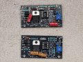
Tachometer suddenly died, wondering if the chip is likely still operational.

Movement on this is 120 degrees, 0-6k RPM. Same T2621 IC and clock spring movement.
I’d suggest, the first step is to check the full scale current of your meter by connecting a potentiometer, maybe 500 ohms in series with the meter and a 5V supply. The internal resistance of the meter coil itself will be small. This will give you the value of resistance you need in series with the meter recognizing that the PWM output from the transistor can be varied between 0 and around 4.7V with analogWrite(). Then, assuming you have two coils, each of which are firing 4 cylinders, I think that sniffing the negative terminal of one coil will give the same number of sparks as a 4 cylinder car per revolution

If you only plan to build one unit I’d consider using strip board although a proper PCB is nice. It may be that the only code you’ll need to change is the linearization table, and an adjustment from 8000 to 6000 RPM
 

Thread Starter

Stuntman225

Joined Apr 28, 2026
76
I’d suggest, the first step is to check the full scale current of your meter by connecting a potentiometer, maybe 500 ohms in series with the meter and a 5V supply. The internal resistance of the meter coil itself will be small. This will give you the value of resistance you need in series with the meter recognizing that the PWM output from the transistor can be varied between 0 and around 4.7V with analogWrite().
That's what I was trying to say but using resistors instead of a potentiometer, a potentiometer would be much easier to use than what i was thinking of.
If you only plan to build one unit I’d consider using strip board although a proper PCB is nice. It may be that the only code you’ll need to change is the linearization table, and an adjustment from 8000 to 6000 RPM
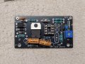
Depending on how the original tachometer received coil neg signal, the only things that should need change is the short pulse ignore length, and interpolation table. A pcb costs $12 with shipping from JLCPCB, so I would buy one. (I may have devolved an addiction to designing circuits and pcbs)
 

Thread Starter

Stuntman225

Joined Apr 28, 2026
76
Update, V2 is built and somewhat works. V2 is a trimmed down version of V1, cutting the Schmitt trigger and adding a capacitor to the opto circuit. With a 4000 pf capacitor, the tach wanders between to differing rpm values, even when the actual rpm stays the same. Better code could fix the problem, and I'll try more caps later, but I ran out of time today. Files will be added to the repo soon.20260810_165144.jpg
 

Attachments

Thread Starter

Stuntman225

Joined Apr 28, 2026
76
I figured out the issues with the inaccurate reading, with the new sensing method I'm using I needed to change the side of which i read pulses in software, so flipping a bit in my code fixed the issue. I haven't gotten a chance to thoroughly test it yet, but the short tests that i did are showing that the new board design is better.
 
Top