To illustrate, tilt threshold and bumper angles are other attributes that contribute to successful play of at able. A wizard knows by muscle memory or feel, what that parameter is on a given table.
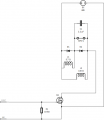
So given the fact that the coil has resistance I1 = 3.7 Ω (powerful "kick") and I2 = 133 Ω (weak "hold") and the plunger is spring loaded. That I have an Arduino to power 5V and a DC power supply to 48V with a power filter/capacitor board, what do I need given the comment below?
My advice for the MOSFET is to go large. By that I mean, if you think you need 10A, spend a fraction more and get 20A. And/or spend to get a lower Rds-on.
Also, the value of R1 will determine (possibly) the discharge rate of the MOSFET gate charge, depending on how the micro +5V pin operates. So, keep the value a bit on the smaller side, like in the 1k ohms range.
If using discrete through the hole MOSFETs, look into ones like the IRL540 which are common and relatively cheap. They are rated 100V and 28A at 25C with a very small RDSon of 0.077 ohms. With 4V on the gate, RDSon rises a bit to 0.11 ohms, but still very low for triggering relay coils
If a faster turn-off is really needed than a small resistor in series with the diode (say equal to the solenoid resistance) will significantly reduce the turn-off time
The trade-off is that it will increase the turn-off voltage across the MOSFET to twice the supply voltage.
Be careful with a 55V MOSFET when you are running/switching a 48V supply. Any spike on the voltage supply itself could damage the MOSFET.
IRF540 is not good for 5V gate voltages, it should be the IRL540 (or equivalent substitute) when using a 5V device to a MOSFET gate
1. No need for flyback diode D3 to protect the MOSFET due to the presence of diode D1 and D2 on the coil assembly
2. Pulldown resistor 1kΩ instead of the generally advised 10kΩ ?
3. Large voltage and current for MOSFET
4. Low RDSon for MOSFET
5. MOSFET that is usable for 5V gate voltages, but how do I figure that out ?
6. A N-channel enhancement-type logic MOSFET
7. As a common ground for the MOSFET, should I use the Arduino GND or the 48V power supply GND?
Since the mosfet is switching the current in the 48 volt circuit, use the 38 volt ground for the main connection, BUT ALSO be sure that the gate control loop ground is low resistance.. So really,you do need both grounds, one for the flipper power loop and one for the MOSFET gate control loop.
Since the mosfet is switching the current in the 48 volt circuit, use the 38 volt ground for the main connection, BUT ALSO be sure that the gate control loop ground is low resistance.. So really,you do need both grounds, one for the flipper power loop and one for the MOSFET gate control loop.
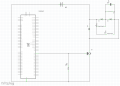
Sorry, I don't understand your comment... In all documentation I found it is mentioned that you need a common ground when using a MOSFET in order to be able to measure the voltages for both circuits. How do you suggest the design should look like inregards to the GND? Now I have the following:
Certainly it is true that the grounds must be common. It is also true that swiching a 3 ohm magnet coil across 48 volts will result in 16 amps flowing for a very short time.And 16 amps flowing through even half an ohm of connection wire resistance will develop 8 volts between the two ground points. THAT is why I suggested separate grounding loops, made common only at the mosfet source terminal. None of the coil current should pass through any of the wires connecting the processor board ground to the flipper current ground.
Keep in mind: Ground loops can KILL attached circuits.
Certainly it is true that the grounds must be common. It is also true that swiching a 3 ohm magnet coil across 48 volts will result in 16 amps flowing for a very short time.And 16 amps flowing through even half an ohm of connection wire resistance will develop 8 volts between the two ground points. THAT is why I suggested separate grounding loops, made common only at the mosfet source terminal. None of the coil current should pass through any of the wires connecting the processor board ground to the flipper current ground.
Keep in mind: Ground loops can KILL attached circuits.
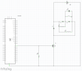
The line from the 48 volt negative supply to the arduino common would be removed, and instead it would go to the mosfet source terminal, or just below the terminal. So the resistor and the mosfet do not need to be so vary far from the arduino, and the entire section with the flipper and diodes could be flipped to the opposite side of D3, then the 48 volt source could be flipped to the righthand side of that vertical line thru D3.
AND, what kind of engineer are you? Your profile says "other".
The line from the 48 volt negative supply to the arduino common would be removed, and instead it would go to the mosfet source terminal, or just below the terminal. So the resistor and the mosfet do not need to be so vary far from the arduino, and the entire section with the flipper and diodes could be flipped to the opposite side of D3, then the 48 volt source could be flipped to the righthand side of that vertical line thru D3.
AND, what kind of engineer are you? Your profile says "other".
So given the fact that the coil has resistance I1 = 3.7 Ω (powerful "kick") and I2 = 133 Ω (weak "hold") and the plunger is spring loaded. That I have an Arduino to power 5V and a DC power supply to 48V with a power filter/capacitor board, what do I need given the comment below?
The circuit in post #51 is much closer. But I would still split the two connections to the source terminal of the mosfet. Other than that, it does reflect much closer to how it should be wired. If the mosfet symbol included a circle to define it as a component then the two lined could come to that dot at the bottom (source) from different directions and the tech assembling the circuit could know just what to do. And this is not even mentioned in the EE classes, it needs to be deduced. The whole concept of "ground" is really novel, and mostly incorrect. "True Ground" is a mythical entity, often mentioned but very seldom seen.
The circuit in post #51 is much closer. But I would still split the two connections to the source terminal of the mosfet. Other than that, it does reflect much closer to how it should be wired. If the mosfet symbol included a circle to define it as a component then the two lined could come to that dot at the bottom (source) from different directions and the tech assembling the circuit could know just what to do. And this is not even mentioned in the EE classes, it needs to be deduced. The whole concept of "ground" is really novel, and mostly incorrect. "True Ground" is a mythical entity, often mentioned but very seldom seen.
The power supply "ground" terminal must be connected to the green wire in the line cord, so that the power supply frame is safely grounded. It has no use in the internal wiring and so it should not connect to any part of the circuit. The power supply negative terminals can be connected to the arduino ground connection.
In this system really there is not a ground, but rather a common, which is the power supply negative terminals.
The power supply "ground" terminal must be connected to the green wire in the line cord, so that the power supply frame is safely grounded. It has no use in the internal wiring and so it should not connect to any part of the circuit. The power supply negative terminals can be connected to the arduino ground connection.
In this system really there is not a ground, but rather a common, which is the power supply negative terminals.
The meanings of words are really quite important and far to often overlooked. That is certainly a source of misunderstanding and results in a lot of confusion. That is why Itry to avoid using the term ground except for the "green wire" portion of electrical distribution systems, where it usually means an actual connection to the earth.
The meanings of words are really quite important and far to often overlooked. That is certainly a source of misunderstanding and results in a lot of confusion. That is why Itry to avoid using the term ground except for the "green wire" portion of electrical distribution systems, where it usually means an actual connection to the earth.
That high lights the terminology I was trained and grew up in, 'Ground' was very rarely used, it was 'Chassis" "Common" etc, for safety, you used "Earth" or maybe the qualifying, "Earth Ground".
It is also aggravated by those that randomly use the earth ground symbol in schematics to indicate the common power rail regardless whether it actually is or not!
Max.
Your terminology clarification really enlightened me! Using that I found proper explanations about what I needed to know:
- MOSFET source needs to be connected to Arduino GND to close 5V circuit
- MOSFET source needs to be connected to power supply V- to close 48V circuit
- Both circuits need to be connected to the Arduino GND to have a common reference point
By knowing this, reading back your comments do make so much more sense! I'm certainly going to update my glossary so that I know (and remember) the right terms to use.

 Facebook
 Google
 GitHub
 Linkedin