How do I choose the correct inductor type and package for a buck converter?

Thread Starter

akash.kumar123

Joined Jul 20, 2026
15
I am designing a buck converter and I understand that the inductance value and current rating are important, but I am not clear about how to choose the physical type and construction of the inductor.

Specifically, how should I decide between:

  • SMD vs. through-hole (THT)
  • Shielded vs. unshielded
  • Different inductor packages/sizes
  • Different core/construction types
I would like to understand the engineering criteria behind the selection, rather than simply choosing an inductor based on the datasheet's recommended value.
 

BobTPH

Joined Jun 5, 2013
11,657
The two driving requirements are inductance and current capability these are musts. Do do a simulation, because the peak current in the inductor may be higher than your output current. Next is resistance. You want as low as possible. But again, use simukation to see how much it affects performance.

All the other things are niceties. If it needs to fit in a small space, you will need physically small inductors, Frequency is your friend here. Higher frequency, lower inductance, smaller size.
 

ronsimpson

Joined Oct 7, 2019
4,820
coilcraft.com has design tools you might want to look in to this.
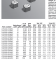
I usually start out looking at datasheets like this.
Here is a data sheet. Looking at the 33uH inductor, when the peak current gets to 360mA the inductance drops 10%, 400mA=20% and 420mA=30%. Inductors start to not be inductors at some current. Stay back off this for your peak.
Note that at 600mA rms the inductor increases 20C. This is not the peak but the rms current.
1789137082800.png

Shielded vs. unshielded
That depends on cost and if the noise will get into something else. Shielded are much quieter.
Different core/construction types
There are different core types. Each core is built for a different job. Some are very temperature and some are not. I usually choose a core by what frequency I am running at.
SMD vs. through-hole
It is getting hard to find TH. This might depend on the company assembling for you. Very large transformers are TH.
 

panic mode

Joined Oct 10, 2011
5,281
  • SMD vs. through-hole (THT)
  • Shielded vs. unshielded
  • Different inductor packages/sizes
  • Different core/construction types
you need to keep in mind what the application is. SMD/THT selection may be influenced by vibrations/shocks that product will experience. THT mount is more rugged.

SMPS generates a lot of noise. shielded coil is a major factor in containing interference. if your application is some sort of energy convertor where interference is not important, go for it. but if the converter is supposed to be near any sensitive circuit, that is a definite no.

normally you would not care about inner details (construction, materials etc) unless application specific. in most cases you would simply pick inductor based on key values (current, inductance, saturation...).

and exception is when using transformers. normally they transfer energy directly but flyback transformer have a gap. this allows them to store energy during short pulse, and release it during off time (time between pulses).
 
Last edited:

MisterBill2

Joined Jan 23, 2018
28,337
The inductor in a "BUCK" type of switcher supply will need to provide the capability to store the required amount of energy as a magnetic field to allow the supply to deliver that energy. The math to do that accurately is some heavy CALCULUS, but an adequate SWAG only takes multiplication and addition. The "close guess" is that the inductor watts rating should match the delivered power rating. The actual INDUCTANCE can be found while doing the circuit design numbers.
 

Ian0

Joined Aug 7, 2020
13,281
No one has yet mentioned that these are inductors that must work on DC. That means that they must have a core with an air gap in order to prevent saturation.
A ferrite (or steel strip) core will have a physical, observable gap with a width that is measurable. An iron powder core relies on the gaps between the particles which are embedded in epoxy resin.
As we are dealing with square waves most of the calculus turns into multiplications.
For a buck regulator proceed as follows.
Choose an operating frequency, and a maximum ripple current (common ripple current choices are 10% or 20% of the maximum output current.
Calculate the period: t=1/f
calculate the on and off times from the ratio of the input and output voltages. d=Vout/Vin.
ton=period*d
This is where the calculus appears. dI/dt=V/L. L is the inductance. but dI/dt is simply the ripple current divided by the off-time.
So Vout/L= Iripple/toff
L=Vout.toff/Iripple
Now you have to find an inductor of the inductance you calculated, which will withstand the peak output current without saturating. (The peak output current is the design output current plus half the ripple current)
 
Top