 Facebook
 Google
 GitHub
 Linkedin
Hello all!
I have a problem where my step-down converter circuit works on my breadboard but not on my PCB. Essentially, I'm using a Teensy 3.2, a stepper motor, a stepper driver, a CANBus driver, and an encoder to be able to control a stepper motor and get position data over CANBus. I have it all wired up on a breadboard and everything works great.
Step-down converter link
I soldered all the SMDs on the PCB with a reflow oven, soldered my Teensy 3.2 straight onto the PCB, and decided to test out my step-down converter with the blink program uploaded on my Teensy. Strangely, the Teensy did not turn on, and a multimeter showed that the Teensy was only receiving around 1.6V instead of the expected 5V (so the Teensy isn't getting enough power). I replicated the same circuit on my breadboard, and the Teensy blinks happily.
I'm stumped. I'm pretty sure my capacitors and diode are in the right direction (particularly my diode--I think my silkscreen is in the wrong direction, and I made sure to match my breadboard exactly). I checked my soldered connections to make sure they were soldered okay with no large resistances, and everything seemed to be soldered fine. I checked my diode with a multimeter, that seems to be working fine. None of my capacitors are shorted. I checked to make sure none of the pins on the IC were bridged--none of them are except for the ON/OFF and GND pins, which was intended (see datasheet). I'm getting an expected 1-2 ohms on my inductor. The step-down converter chip is getting the expected 20-21V.
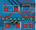
To avoid confusion, I took a snapshot of the area with my my step-down converter (rather than the entire PCB). Ignore all the traces on the bottom layer, the ground plane, and the large through holes that I attach my stepper driver carrier board to. The purple arrow indicates the 5V line that goes to the Teensy. The feedback line goes from the 5V on the 100uF cap to the respective pin on the step-down converter I apologize if it is still confusing or if the circuit design is bad--I'm relatively new to electronics. Please let me know if seeing more of the PCB would be useful.
I guess my question is: Does anyone have any advice on how I can troubleshoot it? Do you think one of the chips was damaged in the reflow oven? To anyone willing to read through the step-down converter IC documentation, could it be something I am doing wrong in my layout?
Thank you in advance!
I have a problem where my step-down converter circuit works on my breadboard but not on my PCB. Essentially, I'm using a Teensy 3.2, a stepper motor, a stepper driver, a CANBus driver, and an encoder to be able to control a stepper motor and get position data over CANBus. I have it all wired up on a breadboard and everything works great.
Step-down converter link
I soldered all the SMDs on the PCB with a reflow oven, soldered my Teensy 3.2 straight onto the PCB, and decided to test out my step-down converter with the blink program uploaded on my Teensy. Strangely, the Teensy did not turn on, and a multimeter showed that the Teensy was only receiving around 1.6V instead of the expected 5V (so the Teensy isn't getting enough power). I replicated the same circuit on my breadboard, and the Teensy blinks happily.
I'm stumped. I'm pretty sure my capacitors and diode are in the right direction (particularly my diode--I think my silkscreen is in the wrong direction, and I made sure to match my breadboard exactly). I checked my soldered connections to make sure they were soldered okay with no large resistances, and everything seemed to be soldered fine. I checked my diode with a multimeter, that seems to be working fine. None of my capacitors are shorted. I checked to make sure none of the pins on the IC were bridged--none of them are except for the ON/OFF and GND pins, which was intended (see datasheet). I'm getting an expected 1-2 ohms on my inductor. The step-down converter chip is getting the expected 20-21V.
To avoid confusion, I took a snapshot of the area with my my step-down converter (rather than the entire PCB). Ignore all the traces on the bottom layer, the ground plane, and the large through holes that I attach my stepper driver carrier board to. The purple arrow indicates the 5V line that goes to the Teensy. The feedback line goes from the 5V on the 100uF cap to the respective pin on the step-down converter I apologize if it is still confusing or if the circuit design is bad--I'm relatively new to electronics. Please let me know if seeing more of the PCB would be useful.
I guess my question is: Does anyone have any advice on how I can troubleshoot it? Do you think one of the chips was damaged in the reflow oven? To anyone willing to read through the step-down converter IC documentation, could it be something I am doing wrong in my layout?
Thank you in advance!
Attachments
-
 320.7 KB Views: 35


