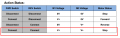
Simple 12Vdc photovoltaic switch for 100 watts motor.

Thread Starter

YankeePirate

Joined Dec 10, 2024
64
SIMULTANEOUS TRIGGER PREVENTION

If for any reason - i.e. sunlight leakage - both phototransistors are triggered t3 and t4 prevent simultaneous triggers.
How might you do this better?
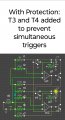

circuitsimultaneousprotection.jpg
 

sghioto

Joined Dec 31, 2017
8,763
Use some feedback to inhibit one side or the other is one possible way.
Not sure exactly but I believe if both outputs are triggered at the same time that motor control relay will ignore the command.
More on this later.
 

sghioto

Joined Dec 31, 2017
8,763
You can see here that the motor will stop if the FWD and REV inputs are both activated.
No additional circuitry is required.
1741279830168.png
 
Last edited:

Thread Starter

YankeePirate

Joined Dec 10, 2024
64
Built boards. Due to eyesight had to make and toss 9 to get 1, each taking 4-6 hours.
Fun.
Connecting trans collectors to F / R caused OONO relay to vibrate/buzz. Unsure if it was a short/open on board removed board and just touched just OONO relay F to ground and then just R. R causes vibration/buzz, like a relay opening and closing at 100hz.

Will go thru my circuit for shorts/opens but unsure if OONO relay is problem.
 

Thread Starter

YankeePirate

Joined Dec 10, 2024
64
What are you using for the 12 volt supply?
Charged motor cycle battery
Already started Amazon return. Will try another unit - same - after exploring a few alternatives. Given my horrid solder and trace wire skills I am using a hydrochloric acid H2O2 etch process with a common Sharpie marker and a long thin one side copper board with this layout I cobbled together. I am going to try to create a Gerber file and get a board made.
When you said "...if you can build it." I thought Jeez I built more complex when younger, but at this point the only way I can avoid flooding and shorting a chip leg or between wired traces is put a measured drop of solder on the iron and delivering it to the junction. Otherwise, it proved an excercise in silversmithing I found humorously challenging. The traced etch might help get a proto built. I do thank you for your patience
etchtrace.jpg
 
Last edited:

sghioto

Joined Dec 31, 2017
8,763
That's not going to work.
You can't change the circuit to fit the pc board design.
R3 and R6 must return to the +12 volt trace somehow.
Are you trying to use all surface mount components?
 

Thread Starter

YankeePirate

Joined Dec 10, 2024
64
That's not going to work.
You can't change the circuit to fit the pc board design.
R3 and R6 must return to the +12 volt trace somehow.
Are you trying to use all surface mount components?
I made a 6 hole x 28 hole bum proto pcb and it was the perfect size as a gum stick to go across a phone screen...the operational position for this with phototrans on each end towards edges. Etching will likely get 2-5 more horizontal tracks so I can collect them on one edge for a cable etc.

Rewired.to original 47k. Different attempts failed.
 

Thread Starter

YankeePirate

Joined Dec 10, 2024
64
I made a 6 hole x 28 hole bum proto pcb and it was the perfect size as a gum stick to go across a phone screen...the operational position for this with phototrans on each end towards edges. Etching will likely get 2-5 more horizontal tracks so I can collect them on one edge for a cable etc.

Rewired.to original 47k. Different attempts failed.
The first gerber file attempt was to figure traces for std components I have. Eventually I suppose I will need surface mount components so I am practicing.
 

Thread Starter

YankeePirate

Joined Dec 10, 2024
64
I don't know, can you solder surface mount components? :p
You are soooooo cute. Solder surf mount? I send pdf to China, wait.7-30 days, they send back ?10?100?.Dunno.
This is a product with Zero sales so will likely etch and solder with a layout like this.
Best so far.bestetchlayout.jpg
 
Last edited:

Thread Starter

YankeePirate

Joined Dec 10, 2024
64
Don't forget pin3 is also connected to pin5.
You are too quick! Ping! Like a science teacher with a stack of quizbestetched.jpgzes..and a BB gun...

11 parts plus fem USB header, 30 holes and joints, 30-60 minutes with etching and assembly. Any bets on a proshop price?
 
Last edited:

Thread Starter

YankeePirate

Joined Dec 10, 2024
64
Don't forget pin3 is also connected to pin5.
And now this.
Perhaps I cannot solder
though miles of copper pipe I've laid
I even took Motherboard dssign
and got an OK grade.
But one thing.I.can do with Zoom
as my eyes reflect my age;
is use a cheap Android photoshop
and with HCL cut a copper page.
bestcleanedetch.jpgbwwetch.jpg
 
Last edited:
Top