Is there a simple Circuit bt which I can identify each pin (EBC) on a Transistor?

Thread Starter

ConstantineOfTexas

Joined Jun 27, 2017
47
I would like a simple circuit with a slot to test a transistor for its E,B, and C pins. This question was brought on by the fact that there are two different pin-outs for 2222 Transistors. Here's how I would like it to work:
The Transistor pops into the testing circuit in a designated pins of a testing slot, say A1, A3, and A5. If the Pins are E,B, and C, respectively, a light goes on. Otherwise, the light stays off. I am not so much concerned about PNP or NPN configurations as I am about EBC and CBE configuration.

Please understand that astigmatism makes it hard to read a transistor, even in the strongest of light.
 

SamR

Joined Mar 19, 2019
5,526
These used to be dirt cheap... Very handy on the bench. Tells you what type of transistor it is and some basic parameters as well as identifying what each leg is. Also does diodes, resistors, coils, capacitors, etc. Far easier than using a multimeter.
1783808098789.png
 

robp1956

Joined Jun 12, 2026
119
These used to be dirt cheap... Very handy on the bench. Tells you what type of transistor it is and some basic parameters as well as identifying what each leg is. Also does diodes, resistors, coils, capacitors, etc. Far easier than using a multimeter.
View attachment 369397
I have a couple of those and they do a great job for the most part. I have not hit a hard limit when testing and Zener I have tested up to 20V. All while running on a 300mAh battery or a single 18650.
 

Thread Starter

ConstantineOfTexas

Joined Jun 27, 2017
47
I was hoping for a DIY Circuit that can be assembled on a Breadboard. If I ordered it, Naggums might use the Rolling Pin on me for spending too much. I'll have to think about it. I do have skads of Electronic Components to work with and was hoping to throw something together quick and dirty. All I want to do is identify the E,B, and C pins regardless of PNP or NPN configuration. I have lots of 2222 transistors. The bad news is that 2222s have two different pinouts. Reading those transistors is hard because of Astigmatism.
 

MisterBill2

Joined Jan 23, 2018
27,977
I have seen, many years ago, a very simple oscillator circut used as a transistor checker. It had a socket for "EBC" and a sockect for "ECB" and a switch for "PNP" or "NPN", which reversed the polarity. There was a light that would come on if the oscillator operated. I think it had a feedback transformer. THAT should be about as simple as it could be.
 

crutschow

Joined Mar 14, 2008
38,669
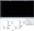
If you are mainly interested in just checking the 2222's you have, here is a simple circuit for that.
Below is its LTspice sim that should work for your 2222 NPN transistors with EBC or CBE pinout.
It depends upon the fact that, even though a transistor can work inverted (collector and emitter interchanged) its gain is very low in the inverted condition.
As you can see from the sim, the inverted LED current (green trace) is much lower then the normal connection (yellow trace) so the difference in LED brightness should indicate the connection orientation.
(The LED light in the inverted configuration should not be visible or barely glowing in normal ambient lighting.
If it's too bright, then you can add a 1kΩ resistor across the LED to shunt the low current and change the series LED resistor to about 600Ω).

Note that the supply voltage should be no greater than 5V, otherwise it could break down the base-emitter junction when operating inverted.
You could use either a USB 5V supply, or three AA/AAA alkalines in series for the power.

To make one for PNP transistors just reverse the battery polarity and the direction of the LED.

By altering the circuit slightly you could use a DPDT switch to go from NPN to PNP using just one circuit.
I can post that circuit if interested.

1783822802915.png
 
Last edited:

crutschow

Joined Mar 14, 2008
38,669
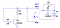
Okay, below is the circuit using a DPDT switch to select for either an NPN or PNP transistor:
I added a resistor across the LED so the inverted transistor connection should give essentially zero current through the LED for any typical value of inverted current gain.

The circuit can also be used to determine if it's NPN or PNP, as the LED won't light in either transistor orientation if the switch setting doesn't correspond to the transistor type.

1783975620180.png
 
Last edited:
Top