Simple 12Vdc photovoltaic switch for 100 watts motor.

Thread Starter

YankeePirate

Joined Dec 10, 2024
64
Senator Crenshaw, a Veteran and man I agree with on occasion and disagree with now&then made one of the most enlightening statements I ever heard and I hope it inspires you, angry insulted engineer, so if someone says something you find offensive, whether in jest or in earnest, you can let it roll off your back like water off a duck. He said "Try not to offend or be offended." - words that hit home to me who grew up near East L.A. where people often got shot or stabbed for something spoken other people would ignore.
Applying the Senator's philosophy to our convo thread, which began with you wondering why a remote controlled boat might be of interest, I implied there are engjneers inclined to recline at home and sail a boat at the same time and humorously injected a reference to nerdy kids, a video game generation to be sure, sitting in parent's basement and poof, you are offended. I apologize if any premise I mentioned does not ring true to you. I teach tech kids so perhaps I am more familiar with that crowd. As for on site command of a vessel, I did not cover the camera requirements of such a.system but will explore with a drone expert: thanks for the tip.
Senator Crenshaw, a Veteran and man I agree with on occasion and disagree with now&then made one of the most enlightening statements I ever heard and I hope it inspires you, angry insulted engineer, so if someone says something you find offensive, whether in jest or in earnest, you can let it roll off your back like water off a duck. He said "Try not to offend or be offended." - words that hit home to me who grew up near East L.A. where people often got shot or stabbed for something spoken other people would ignore.
Applying the Senator's philosophy to our convo thread, which began with you wondering why a remote controlled boat might be of interest, I implied there are engjneers inclined to recline at home and sail a boat at the same time and humorously injected a reference to nerdy kids, a video game generation to be sure, sitting in parent's basement and poof, you are offended. I apologize if any premise I mentioned does not ring true to you. I teach tech kids so perhaps I am more familiar with that crowd. As for on site command of a vessel, I did not cover the camera requirements of such a.system but will explore with a drone expert: thanks for the tip.
Furthermore, perhaps my real life experience might have tainted my reply and humor. 40+ years ago, right before 2D PONG, BREAKOUT, ASTEROIDS and PAC MAN while building my first robotics systems I lived with Mark Froelick who designed 1,000s of NOAA ocean buoys tracking wave and weather data. They ran for years on 4 DD batteries, blipping a short data signal to satellites every 60 seconds. Mark, pushing 40 years old, looked like a happy smiling pudgy bald teenage kid at his desk under a big bookshelf of vendor&design books...in our basement...and inspired me to always try to emulate his adventurous spirit...so to this day when asked how old I am my answer is always "13".
 

MisterBill2

Joined Jan 23, 2018
28,060
I was offended, not angry, nor terribly insulted. A dumb stereotype image reference is a petty little thing. So the total result was my comment, and that was the end of it. And as for age, I always tell those wanting to sell me medicare ripoffs that I am only 42. That is a nice number that rolls off the lips easily and shuts them up. And a desk in a parents basement would not have adequate resources for what I have done these many years.

There is a HUGE difference between those who simply "do engineering for a living" and those who ACTUALLY ARE ENGINEERS, 24/7/365!
 
Last edited:

Thread Starter

YankeePirate

Joined Dec 10, 2024
64
Read most of this thread but to be clear the light sensors are to be mounted on the phone screen inside the water proof enclosure?

Simple circuit is available if you are able to construct it.
View attachment 339833
TESTING LDR: when held against smartphone screen resistance ranges from infinite (black) to 32K (white/40% brightness) and 15K (white/100% brightness) and 160 ohms when hit with bright phone flashlight (not used)

How does that affect 4.7K or 10K resistors? Thank you.
 

Thread Starter

YankeePirate

Joined Dec 10, 2024
64
I was offended, not angry, nor terribly insulted. A dumb stereotype image reference is a petty little thing. So the total result was my comment, and that was the end of it. And as for age, I always tell those wanting to sell me medicare ripoffs that I am only 42. That is a nice number that rolls off the lips easily and shuts them up. And a desk in a parents basement would not have adequate resources for what I have done these many years.

There is a HUGE difference between those who simply "do engineering for a living" and those who ACTUALLY ARE ENGINEERS, 24/7/365!
I am an engineer 23/6/364 since taking time to laugh at myself&peers is a key to brilliance.
 

sghioto

Joined Dec 31, 2017
8,740
TESTING LDR: when held against smartphone screen resistance ranges from infinite (black) to 32K (white/40% brightness) and 15K (white/100% brightness) and 160 ohms when hit with bright phone flashlight (not used)

How does that affect 4.7K or 10K resistors? Thank you.
Change R3 and R5 to a 47K resistor. This will trigger the output at 32K or 15K LDR resistance.
R4 and R6 remain at 4.7K.
 

Thread Starter

YankeePirate

Joined Dec 10, 2024
64
Change R3 and R5 to a 47K resistor. This will trigger the output at 32K or 15K LDR resistance.
R4 and R6 remain at 4.7K.
Thank you. Ordered parts. Got breadboard. Having flashback to college microcircuitry class. Trying to plan breadboard and PCB layouts. Will send photo when working. My soldering sucks.
 

BobaMosfet

Joined Jul 1, 2009
2,211
I assume a 12vdc battery driving a linear actuator (gear motor and allthread) based on a signal a photovoltaic transistor would soon cook the transistor and wondered if the little 12vdc relays I had used before plus a 100ohm resistor (I think) on the transistor would protect it. I assume the motor will pull 8 amps or about 100watts max. Is there a better more durable or solid state power switch than those relays and does 100ohm sound like the right size?
IRLZ44N

Just make sure you do the thermal (Pd) dissipation calcs. But it can handle it. Put a big heatsink on it if necessary ;) Put a flyback around the load to protect the FET.
Wattage:

P = IE
P = 8 * 12
P = 96 Watts

Load Resistance:

R = E/I
R = 12/8
R = 1.5 Ohm (approximate DC load resistance- you can get more accurate, but this will work).

How you control it with a photo-voltaic is up to your skill & creativity ;)
 

Attachments

Thread Starter

YankeePirate

Joined Dec 10, 2024
64
IRLZ44N

Just make sure you do the thermal (Pd) dissipation calcs. But it can handle it. Put a big heatsink on it if necessary ;) Put a flyback around the load to protect the FET.
Wattage:

P = IE
P = 8 * 12
P = 96 Watts

Load Resistance:

R = E/I
R = 12/8
R = 1.5 Ohm (approximate DC load resistance- you can get more accurate, but this will work).

How you control it with a photo-voltaic is up to your skill & creativity ;)
Thank you for the tip Boba...but I do not believe this applies to the current circuit being built. This photo transistor circuit simply drives a prefab motor controller and while that may get warm, its outside in a sailboat cockpit and we'll likely stuff it in a small grounded aluminum box with a watertight user serviceable endcap. The phototransistors will be on a plastic bar embedded in a spandex velcro leash or adjustable phone clip to lock it on any smartphone. Right now we're shrinking the circuit so it can sit on the phone clip instead of at the motor controller which might be 10 feet away.
 

Thread Starter

YankeePirate

Joined Dec 10, 2024
64
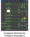
LM393 CIRCUIT APPEARED TO BE 2 OP AMPS.

Circuit simulator did not have LM393 so I built this with Op Amps in appropriate places.

Physical breadboard build using 47K resistors failed: possible cause is fumbly fingers and poor eyesight. It has been 30 years since breadboard was dug out. Soldering will likely be painful.

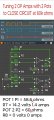
To verify values I built circuit simulator and inserted 2 POTENTIOMETERS to replace 2 Phototransistor with the goal of triggering transistors around 50-60k ohms. This way any reasonable light from phone will cause voltage and current at R7 and/or R8.

Setting POT 1 at 58.6K ohms closed circuit at R7, while POT 2 at 60K ohms did not close circuit at R8. I need to ensure both do not simultaneously trigger.

NOTE: 60 ohms should read 60K in drawing and 58.6 = 58.6K.

Increasing R7 or R8 limited current to milliamps. Decreasing R7 or R8 allowed up to 1.5 amps to flow.

I will fine tune more after motor controller arrives.circuitsim.jpg
 
Last edited:

sghioto

Joined Dec 31, 2017
8,740
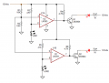
The LM393 is a dual comparator chip. Strange that's not in the library as that chip has been around for over 40 years or more.
 

sghioto

Joined Dec 31, 2017
8,740
The resistance readings listed in post#63 should work fine with the 47K resistor unless something has changed.
I suggest trying again on the breadboard using a LED for verification.
1741200757829.png
 

Thread Starter

YankeePirate

Joined Dec 10, 2024
64
The resistance readings listed in post#63 should work fine with the 47K resistor unless something has changed.
I suggest trying again on the breadboard using a LED for verification.
View attachment 343823
Thank you for updated drawing. Drop by Half Moon Bay/Silicon Valley so I can buy you a burger and a beer.

I will retry build with your circuit, but will solder to ensure crusty breadboard (purchased in ?1985?) is not a problem AND I need practice soldering AND we will have actual motor control signals for inputs.

I also studied how to make PCB etching with ferric chloride and also using H2O2 and hydrochloric acid and how to transfer circuit schematic to single sided board before etching, and how to make them freehand with a Sharpie marker.

Gonna get real interesting.
 

Thread Starter

YankeePirate

Joined Dec 10, 2024
64
The resistance readings listed in post#63 should work fine with the 47K resistor unless something has changed.
I suggest trying again on the breadboard using a LED for verification.
View attachment 343823
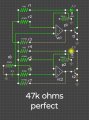
Rebuilt Simulation with LEDs and 47K resistors (your original upgrade A).

Transistor Trigger now 94k ohms on Pot: the adjustable proxy for Phototransistors.

This may be fine. Will retest/adjust 47K and 4.7K resistors in simulator.

...waiting for controller & boards


circuitsim47k.jpg
 

sghioto

Joined Dec 31, 2017
8,740
That's not the correct circuit.
You show an additional 10k resistor on the plus inputs of both circuits.
That third resistor (10k) down from the top should be removed.
Always label components. For resistors use R1 and so on.
In the sim the pots should start at max resistance say 100K so both LEDs will be OFF.
The LEDs should lite when the pots are slightly below 47K.
1741209265005.png
 
Last edited:

Thread Starter

YankeePirate

Joined Dec 10, 2024
64
That's not the correct circuit.
You show an additional 10k resistor on the plus inputs of both circuits.
That third resistor (10k) down from the top should be removed.
Always label components. For resistors use R1 and so on.
In the sim the pots should start at max resistance say 100K so both LEDs will be OFF.
The LEDs should lite when the pots are slightly below 47K.
View attachment 343836
Thank you for spotting 10K.
Your circuit appears to nail 47k.
Now I have to build it
circuitperfect.jpg
 
Top