There are some major differences that I see between using a screen display on a cell phone and a bluetooth device, and the big difference is control range. If I had that app to control the display on my phone, I could control that actuator from here, even if it were in the gulf of Mexico.
What has not been discussed at all is the gain stage of the control scheme that will be needed between the screen sensor elements and the power control transistors.
Certainly there will need to be some amplifier to allow a signal of a few millivolts to drive mosfets switching several amps of 12 volt DC power. It seems that so far that segment of the control system has not been considered.
There are some major differences that I see between using a screen display on a cell phone and a bluetooth device, and the big difference is control range. If I had that app to control the display on my phone, I could control that actuator from here, even if it were in the gulf of Mexico.
What has not been discussed at all is the gain stage of the control scheme that will be needed between the screen sensor elements and the power control transistors.
Certainly there will need to be some amplifier to allow a signal of a few millivolts to drive mosfets switching several amps of 12 volt DC power. It seems that so far that segment of the control system has not been considered.
Agreed. Assuming a 15ft USB cable delivers 5volts to band with photo transistors don't know what.amperage can be returned. Later, once tested with cable I can play with RF/Bluetooth and Wifi, but signal connections almost always require.human intervention and remote as you suggest requires Starlink or coastal wifi and more human interactions. Once a working LIGHT DETECTOR is chosen and AMPLIFIER and cable is made then I can test it with a prefab motor controller for $13-$25. You folks taught me building that from scratch is more expensive than buying one already done. I still need to pick the parts for that and aim to feed a signal into something like this. They say SINGLE CHANNEL.OR TWO CHANNEL so I assume that is motor.on/off or motor fwd/rev.
Once done I can update software to do things like relay speed and possibly depth and wind speed with a bit more circuit capturing NMEA data from instruments.
What would that USB cable be connected to??? I seem to have missed that part.
I see an immediate issue in the the USB specification probably does not address very low level analog signals. So once again we are back to that intermediate amplification segment that has been mentioned but only described in very general terms, by what it needs to provide, with no details.
What would that USB cable be connected to??? I seem to have missed that part.
I see an immediate issue in the the USB specification probably does not address very low level analog signals. So once again we are back to that intermediate amplification segment that has been mentioned but only described in very general terms, by what it needs to provide, with no details.
Cable supplies voltage from 12volts at autohelm actuator to light sensors which would return on either 2 data lines in USB cable (fwd/rev) or single cable + or - which would require a ground, so 3 wire minimum, or 4 in common USB cable. Thin wires and 15 ft length (30 ft round trip) may cause amperage issue requiring amplifier at light sensor. Goal is to give skipper easy common part to replace if damaged. Other goals include cheap spares; the motor controller and light sensor band, so if something fries they can easily swap/plug in a new one from spares in a bag.
Calculations and creating parts-lists, doing searches, creating custom Schematics, all takes TIME.
When starting from scratch, without a basic overview of what is practical, and what is possible,
it could easily take a year before a final plan is decided upon.
The mention of a ~15-foot USB-Cable has me in a spin.
If You're going to run a Cable across the room, it would be more advantageous to
just run a piece of Cat-6 Cable.
But USB ???????
.
.
.
Calculations and creating parts-lists, doing searches, creating custom Schematics, all takes TIME.
When starting from scratch, without a basic overview of what is practical, and what is possible,
it could easily take a year before a final plan is decided upon.
The mention of a ~15-foot USB-Cable has me in a spin.
If You're going to run a Cable across the room, it would be more advantageous to
just run a piece of Cat-6 Cable.
But USB ???????
.
.
.
I think any 4 conductor black water resistant/proof cable or Cat 6 would be a huge asset vs USB, the problem being ease of replacement on the fly,.though a 3 conductor orange extension cord is a commonly held/found/made device if the light sensor can use a 12v supply, plus 2 lines that can easily flip hot and ground or have a constant hot/ground and 3rd wire +12v or ground (fwd/rev) or open (off). That would eliminate a danger I read about.firing fwd.and rev at the same time.
In short, you're not.wrong to dismiss a 15 ft USB for several reasons and I am a newbie but not so stupid as to embed a known defect that costs more, delivers less and can't be easily replaced by a skipper on the fly.
As for time to fine tune a prototype, I've been down this path dozens of times for 50 years and am pretty good at following a "SCRUM" accelerated protype process where quickie versions 1-5 are aborts but provide great data and concrete reasons for final component selection, which determines final design.
Today, we solved the motor controller assembly. Thank you. The use of $40-$60 of chips vs a prebuilt board for $15-$25 with built-in heat sink is a no brainer.
Yesterday, we discovered an engineer with a little passion to get thru the cable design working, and followup with a bluetooth or wifi model. Great. I have a pal who does robotics for Meta and he recommends those designs as well, but he's near useless for circuit designs.
Tomorrow (and today) I had hoped to pick light sensors; easy to test with any white screen area of a smart phone. Mounting it into a surfers.ankle leash or thinner band with grommets to adjust circumference and elastic (rubber band) for tension, plus black PL Roof and Flashing polyurethane (we patch boats with this stuff and it's tough, flexible and waterproof) would make a durable unit. The fat UL plug of a 3 wire orange (or black) cord would be butt ugly but for a prototype it'd work.
Since that line could have a 12v feed (instead of 5v) adding a cigarette style charger and 12v USB charger.and short USB cable to keep phone charged delivers that feature despite changing.cords away from USB.
This only leaves light sensor circuit, and package that's either a dongle hanging off band, or small box or lump on cord/accepting cord or plug, with circuitry inside, or build circuit into the band and cover with rubber. I think dongle will be prototype 1.
So we come to the logic challenge; can a 3 wire cord deliver logic fed to a box at the actuator to fwd/rev a motor? I suggested a 12v feed and ground, plus a signal line that is either +12v (fwd) ground (rev) or open (off) though I understand the tendency and ease of design might suggest a 12v feed and 2 lines that are flip 12 and ground or are off.
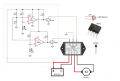
Yes; at this phase many forks come and go until the appropriate sensor is designed. The circuit shows an LM350 (top left) and I still don't know what resistor to use or even the light sensor. My bucket of 30 yo parts, diodes, caps & more stuff I have no idea, is being enhanced with a new assortment of resistors. Other items recently bought like N channel mosfets will sit in waiting or not get used.
But your ideas do get used. I'm only a stubborn fool half the time.
REFLECTING on actuator -> 2 wires (i.e. orange cord) -> dongle with board inside + cig.plug&phone charger+12v supply&ground (orange cord) I think I eliminated 3 wire cord & eliminated circuits at actuator can deliver a light durable waterproof box, the big problem now being connecting 2 wires to output of 2 channel board (4 wires/2 pairs with opposing polarities) feeding 2 wires to actuator; Diodes?
This would produce a clean box with a useful plug and circuits.and.12v feed set near phone, not at actuator.
OK,I see the amazon relay module and I see not one word about how much current it can control and have a reasonable lifetime before the contacts fail. Nor do I see any comment about how much current the relay coils require. So there are quite a few rather important details not mentioned at all.
New Topic:
I think that I got the impression that the setup was for steering a boat. Was that correct? or am I confused???
OK,I see the amazon relay module and I see not one word about how much current it can control and have a reasonable lifetime before the contacts fail. Nor do I see any comment about how much current the relay coils require. So there are quite a few rather important details not mentioned at all.
New Topic:
I think that I got the impression that the setup was for steering a boat. Was that correct? or am I confused???
The first ones says 10 amps. Others vary from 3.6 up to 20. The current actuator on hand wants 3 amps. Larger units want 5-8. I think you two gentlemen and a guy at another forum who taught me the H bridge.circuit did a fine job of convincing me:
a) Its cheaper and probably more reliable to buy prefab (less than half the cost) and
b) running a 15ft USB from actuator to phone/light sensors is a fatal expensive mistake and is best solved by using 2 conductor black cord from a sealed dongle box with circuits inside, protected from seawater, carrying current to actuator, plus a 12v input cord to box, plus a short cable to phone sensors or building a box with a PHONE CLIP and light sensors inside and one clear side to allow light in; all waterproof.
I am afraid our friend who wisely pressed me for the cord modifications has given up after his rant about "a year to.prototype" which I believe is grossly exaggerated.
At this point only the unknown light sensors remain unclear, shown with an LM350 and unknown resistor in circuit diagram. Yes, this pushes an actuator for autopilot tiller function, but as you wisely noted it has a multitude of applications by embedding an array into box, like start/stop/throttle engine, and sensor data, like engine temp, wind speed and direction, AIS etc. All of that would likely require 6 months to a year to incorporate along with a web.server to allow you to control a sailboat in Mexico from a cabin in Montana.
And yes, I.intend to explore that after finalizing version 1, self-contained onboard steers boat. Period.
Current stumbling block is light sensors; at the heart of the unit. The original idea was an elastic band around phone but I see the need to bury the controller in a watertight box and that can eliminate a cable to the phone by embedding the light sensors and a phone clip in the box. Ideally a light plastic waterproof box like those used for outdoor swimming pools and AC would work with a clear panel or 2 drilled holes for light sensors or small clear removeable plugs that house light sensors.and fit into 2 box holes.
Picking sensors will determine what's possible. I do appreciate your fortitude and suggestions even from frustrated engineers who may come and go; its not that complicated a task.
In THIS century the number of goofy guys who want to fly airplanes and fish for salmon from their couch is only exceeded slightly by the number of engineers telecommuting from their parent's basement.
A white duraplastic box w 2 grommets for 2) 2 conductor wires in a rubber shroud connects an autopilot actuator and a 12v supply. The box has a sliding clamp on back to secure phone.and an optional round bar clamp or desk mount. When phone is secured light sensors cover the lower 2-3 cm of the screen in a black dark spandex/nylon bag with a small hole for a charger cable. The upper sliding or spring clip clamp grabs and locks the phone so most of the screen shows and can be swiped. IF that fails a seperate short cable separate 3 conductor elastic band can be made for the light sensors and the common 0V line with the rest of the circuit in the box.with a motor controller.
40 years ago I had.AC/DC college classes 1&2 and microcircuits 1&2 as the 8088.and 8086 were being invented. So there was a time when this would be easy.
Today I know a guy who soldered tiny components for a living using a jewelers glass and he said he'd do a board after I breadboard it so we shall see about what kind of layout we come up with!
In THIS century the number of goofy guys who want to fly airplanes and fish for salmon from their couch is only exceeded slightly by the number of engineers telecommuting from their parent's basement.
I regard that as an insult!! I am, and have been for a lot of years, an engineer working at my employer's sites. The portrayal as some sort of antiquated nerd is quite offensive.
The reality is that piloting a boat of almost any sort requires attention, and cobbling a scheme to do it from a cell phone seems to be a rather poor choice no mater what.
I regard that as an insult!! I am, and have been for a lot of years, an engineer working at my employer's sites. The portrayal as some sort of antiquated nerd is quite offensive.
The reality is that piloting a boat of almost any sort requires attention, and cobbling a scheme to do it from a cell phone seems to be a rather poor choice no mater what.
Senator Crenshaw, a Veteran and man I agree with on occasion and disagree with now&then made one of the most enlightening statements I ever heard and I hope it inspires you, angry insulted engineer, so if someone says something you find offensive, whether in jest or in earnest, you can let it roll off your back like water off a duck. He said "Try not to offend or be offended." - words that hit home to me who grew up near East L.A. where people often got shot or stabbed for something spoken other people would ignore.
Applying the Senator's philosophy to our convo thread, which began with you wondering why a remote controlled boat might be of interest, I implied there are engjneers inclined to recline at home and sail a boat at the same time and humorously injected a reference to nerdy kids, a video game generation to be sure, sitting in parent's basement and poof, you are offended. I apologize if any premise I mentioned does not ring true to you. I teach tech kids so perhaps I am more familiar with that crowd. As for on site command of a vessel, I did not cover the camera requirements of such a.system but will explore with a drone expert: thanks for the tip.

 Facebook
 Google
 GitHub
 Linkedin