Simple 12Vdc photovoltaic switch for 100 watts motor.

Thread Starter

YankeePirate

Joined Dec 10, 2024
64
Really, the sensing could be done using the photo-voltaic solar cells that have been around for over 50 years. Those flat-plate cells generate a bit of voltage when illuminated. Of course there will be some amplification required, but that is the easy part. Getting the phone to display such a screen will be the challenge part.
I see that this scheme will allow remote control in a non-tracable, non-jamable manner from a non-trackable transmitter anywhere in the world, almost. Quite interesting indeed. Somebody could pilot a drone of fair size, or even a twin-engine plane, from anywhere. The feedback could be from another phone camera inside the plane, looking out.
Very interesting indeed.
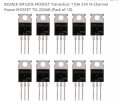
Hope this helps. Any resistors required? Can a circuit be added to ensure if both signals are high no signal is used? Is amp rating of transistors sufficient to drive 5bdc down 15 ft cable? I want all circuits at the actuator so the 5 vdc l7805 delivers 1.5Amps. Can I apply 12vdc to the collector? When 5vdc returns I need to step it back up to 12vdc and was intending to use bd139 bd140 shown in circuit and drive the MOSFET IRF3205 to run the motor. Does this make sense?irf3205.jpg

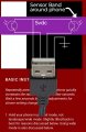
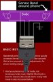
phoneband.jpgScreenshot_20250103-073036.png
 

Attachments

Last edited by a moderator:

Thread Starter

YankeePirate

Joined Dec 10, 2024
64
I really don't know what THE STUPID amazon ad was all about, and I care even less.

Give it a try and then be sure to tell the computer repair place how you damaged it so they know what section to replace. That will reduce the repair cost a bit. ( notice that I NEVER EVEN HINTED that it would work.)
My apology. I thought this was a circuit/component discussion. The parts shown are related to the circuit jpg thingy with lines connecting parts. No worries.
 

MisterBill2

Joined Jan 23, 2018
28,032
My apologies for going off the deep end! The amazon misrepresentation about that transistor set me off. It was totally not the way I choose to respond to folks..

Those TO-220 mosfets might survive 110amps for a microsecond, but not much longer. So the amazon part ad is not any useful information. None at all. It is just an intentionally misleading take-out from the actual data sheet. THAT is what got me upset. And data sheets do give the momentary overload specifications because that matters in some applications. But to present that one spec of data to an average person is very much an intentional lie.
There are useful data sheets for these parts, but you will not find them on amazon.


I am quite willing to discuss circuits, and what can work and what is incomplete. And I am aware that some folks find all sorts of great deals there.
My experiences are quite different. I see advertising created to mislead people and sell products that are not able to deliver what is implied but never stated . And as a result I am accused of confusing folks.
In this thread, sensing colors on a cell phone screen to implement a control function.
YES, I see that the screen can be sensed as described, BUT there would be quite a bit of circuitry in between. It seems that the application is to use a very small amount of power to control quite a lot of power. Certainly that can be done. BUT there is quite a bit in between.

Like in a car: there is quite a bit between stepping on a pedal and the wheels stopping the car from moving. Yes, it works very well, but there is a lot in between.
 
Last edited:

LowQCab

Joined Nov 6, 2012
5,101
MisterBill2
I had the same assumptions,
that this was a hobbyist who got his information from China.


YankeePirate
MOSFETs are not marketed by way of a Wattage-Rating like an old-school Light-Bulb,
They are somewhat complex devices that may require careful selection to suit the application,
that's why there are thousands of different part-numbers.

This project is probably not going to work the way You have envisioned.
I would say it's totally impossible,
but I would probably have several people jump on my head for being too literal.

There are Cell-Phone apps that will allow You to control almost anything with a Blue-Tooth connection.
This would be my recommendation.
And, You need to be much more skeptical of what You find on the Internet,
especially if the price is "Too-Good-to-be-True", because it probably is.
.
.
.
 

MisterBill2

Joined Jan 23, 2018
28,032
For that control project. It is the portion between the sensor and the actuator that has not yet been discussed, and will certainly be "a bit involved" between sensing colors on a cell phone screen and driving a linear actuator. Really, white on each side and black dark in the middle will work better. but probably not into a USB cable.
 

Thread Starter

YankeePirate

Joined Dec 10, 2024
64
For that control project. It is the portion between the sensor and the actuator that has not yet been discussed, and will certainly be "a bit involved" between sensing colors on a cell phone screen and driving a linear actuator. Really, white on each side and black dark in the middle will work better. but probably not into a USB cable.
I updated the circuit adding 2 MOSFETS to handle the ground strap in fwd/rev triggered by the same line triggering the reapective positive gate.
The motor is 3A 12v 36watts. Mosfets are 80watts. Motors are momentary; 2-5 seconds ob, 2-5 seconds off.

I assumed this was easy duty with a 36watt motor and 80watt Mosfet. My worry is putting appropriate resistors and transistors in upper and middle circuits. My second worry is increasing motor size to 5A-7A or 48-84 watts. I figured I could add parallel Mosfets?

I did similar jobs-windshield wiper motors-with relays but was aiming for a "solid state" device.

New circuit with fwd&rev motor ground. Can an incoming 5vdc gate signal be shared between 2.mosfets discharging a 12vdc source and would a 12vdc be wiser? I also bought some optoisolators. Perhaps 5vdc coming from phototransistor can trigger that to supply a 12vdc gate.signal...or is that not required?
 

Attachments

MisterBill2

Joined Jan 23, 2018
28,032
Do the math: If the gate to source voltages are correct then the correct mosfets will switch on. BUT it looks to me like the top mosfet source voltage is different from the lower mosfet source voltage. There are different schemes to drive the "H" bridge, some work very well.
 

Thread Starter

YankeePirate

Joined Dec 10, 2024
64
Do the math: If the gate to source voltages are correct then the correct mosfets will switch on. BUT it looks to me like the top mosfet source voltage is different from the lower mosfet source voltage. There are different schemes to drive the "H" bridge, some work very well.
I know nothing about MOSFETS; studying data sheets.now. Ordered 10 N channels good for ?110amps?
It appears the difference between Gate and Source determines current. I was just trying to get a transistor that can handle 12v 10amps for years.
Will try various gate voltages by swapping resistors and try a 5vdc regulator.
Also most/many diagrams describe audio amplification, 2 mosfets catching high/low +/- sign waves to move speakers.
Someone told me I needed them and what I need is a.gate trigger that allows a source to flow to power a motor....I think.
 

Thread Starter

YankeePirate

Joined Dec 10, 2024
64
Do the math: If the gate to source voltages are correct then the correct mosfets will switch on. BUT it looks to me like the top mosfet source voltage is different from the lower mosfet source voltage. There are different schemes to drive the "H" bridge, some work very well.
I the circuit lower mosfet sees 12v before a motor and upper mosfet sees whatever is left...likely ground 0 or .1 volts. I see what you mean.
Resistance and current would be vastly different.
 

Thread Starter

YankeePirate

Joined Dec 10, 2024
64
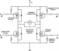
Thank you. The H Bridge article suggests the entire circuit exists in a single package. What is confusing is A A' B B' ?where is input/output. Will try tracing performance.H-Bridge-Configuration.png
 

LowQCab

Joined Nov 6, 2012
5,101
For the Power-Switching-Section of this project,
which is the easiest part,
and which would be easier still if You went with 3-Cube-Relays,
but I understand that You want to go all Solid-State, so OK fine, that's what You want.

Since that's the case, the Circuit that I provided a Schematic for in Post#11
is the easiest to understand, and the hardest to make a mistake in building and implementing.

Then we can start with implementing a Blue-Tooth-Receiver to operate it.

The next question that must be answered is ............
Are You married to the idea of using your Cell-Phone ?,
or would You consider using a small Remote-Control with Buttons on it ?

Either one can work just fine,
but the steep-learning-curve of programming an App on your Phone
may be more than You want to deal with.
It's your call.
.
.
.
 

Thread Starter

YankeePirate

Joined Dec 10, 2024
64
For the Power-Switching-Section of this project,
which is the easiest part,
and which would be easier still if You went with 3-Cube-Relays,
but I understand that You want to go all Solid-State, so OK fine, that's what You want.

Since that's the case, the Circuit that I provided a Schematic for in Post#11
is the easiest to understand, and the hardest to make a mistake in building and implementing.

Then we can start with implementing a Blue-Tooth-Receiver to operate it.

The next question that must be answered is ............
Are You married to the idea of using your Cell-Phone ?,
or would You consider using a small Remote-Control with Buttons on it ?

Either one can work just fine,
but the steep-learning-curve of programming an App on your Phone
may be more than You want to deal with.
It's your call.
.
.
.
Blue Tooth and/or Wifi may be implemented later; for now the use of 2).phototransistors and a cabled device is the plan for other reasons.

As for software that part is easy for me.

I will look at.#11. I used cube relays before and they work for years, but powering this in a solid state package eliminates some iasues including corroaion.
 

Thread Starter

YankeePirate

Joined Dec 10, 2024
64
Reviewing #11 images, unsure.how.FDA215. chips are.uaed.
It appears blue and red squares are diodes. Unsure where 5vdc signal A (fwd) and.signal B (rev) are applied; switches on left?

The ?mosfets? are N doped?
For the Power-Switching-Section of this project,
which is the easiest part,
and which would be easier still if You went with 3-Cube-Relays,
but I understand that You want to go all Solid-State, so OK fine, that's what You want.

Since that's the case, the Circuit that I provided a Schematic for in Post#11
is the easiest to understand, and the hardest to make a mistake in building and implementing.

Then we can start with implementing a Blue-Tooth-Receiver to operate it.

The next question that must be answered is ............
Are You married to the idea of using your Cell-Phone ?,
or would You consider using a small Remote-Control with Buttons on it ?

Either one can work just fine,
but the steep-learning-curve of programming an App on your Phone
may be more than You want to deal with.
It's your call.
.
.
.
FDA215 and CL520 from Mouser.are $5.50 each X 4? 8? or $50 (with 4 more on right side?) and producing ?10vdc? Spec shows 8vdc?

CL520 at .60 cents TO220 package looks right. FDA215 has flat feet.for soldering so I.guess.I.need a ?chip saddle? for breadboard testing.
 

Attachments

Last edited:

Thread Starter

YankeePirate

Joined Dec 10, 2024
64
For the Power-Switching-Section of this project,
which is the easiest part,
and which would be easier still if You went with 3-Cube-Relays,
but I understand that You want to go all Solid-State, so OK fine, that's what You want.

Since that's the case, the Circuit that I provided a Schematic for in Post#11
is the easiest to understand, and the hardest to make a mistake in building and implementing.

Then we can start with implementing a Blue-Tooth-Receiver to operate it.

The next question that must be answered is ............
Are You married to the idea of using your Cell-Phone ?,
or would You consider using a small Remote-Control with Buttons on it ?

Either one can work just fine,
but the steep-learning-curve of programming an App on your Phone
may be more than You want to deal with.
It's your call.
.
.
.
The H Bridge method seemed simpler and I.found this. Thoughts? 50 amps. Done. $13
3.6 amps for $6
 

Attachments

Last edited:

LowQCab

Joined Nov 6, 2012
5,101
Reviewing #11 images, unsure.how.FDA215. chips are.uaed.
It appears blue and red squares are diodes. Unsure where 5vdc signal A (fwd) and.signal B (rev) are applied; switches on left?

The ?mosfets? are N doped?
FDA215 and CL520 from Mouser.are $5.50 each X 4? 8? or $50 (with 4 more on right side?) and producing ?10vdc? Spec shows 8vdc?

CL520 at .60 cents TO220 package looks right. FDA215 has flat feet.for soldering so I.guess.I.need a ?chip saddle? for breadboard testing.
.
CL520 are $0.60 cents each from DigiKey and are only for providing Current-Limiting for
the LED-half of the FDA215's. They are available in TO-92-Packages.
The CL520's may be replaced with properly sized Resistors if
You have a Regulated, and well Filtered, Power-Supply.
But, they are cheap,
and they reduce the hassle of getting the Resistors sized right
when You don't have a large selection to choose from, and,
there might be 2 configurations or more.
They also don''t care about having a sloppy Power-Supply, ( as long as it's over ~6-Volts ),
and they will always only allow 20mA of Current to pass through,
protecting the LEDs against any spikes or other Power-Supply anomalies,
so they are worth the extra effort.

FDA215's are 8-Pin DIP-Packages,
and are Dual-MOSFET-Drivers which may be connected in series for 16-Volts.

If 16-Volts of Gate-Drive-Voltage is calculated to be necessary for the best performance and safety of
the FETs that You have already purchased, then 4 - FDA-215's will be required at ~$5.22 each from DigiKey.

If it is deemed that your FETs will operate satisfactorily on 8-Volts,
then only 2 - FDA-215's will be required.

I haven't checked-out the Spec-Sheet for your FETs so I can't make that call yet.
I will check them-out Saturday when I get a chance.
You may have counterfeit FETs with questionable Specifications,
this is a very big problem with Semiconductors bought from China.

All Semiconductors should be purchased from reputable Electronics Suppliers.
.
.
.
 

Thread Starter

YankeePirate

Joined Dec 10, 2024
64
.
CL520 are $0.60 cents each from DigiKey and are only for providing Current-Limiting for
the LED-half of the FDA215's. They are available in TO-92-Packages.
The CL520's may be replaced with properly sized Resistors if
You have a Regulated, and well Filtered, Power-Supply.
But, they are cheap,
and they reduce the hassle of getting the Resistors sized right
when You don't have a large selection to choose from, and,
there might be 2 configurations or more.
They also don''t care about having a sloppy Power-Supply, ( as long as it's over ~6-Volts ),
and they will always only allow 20mA of Current to pass through,
protecting the LEDs against any spikes or other Power-Supply anomalies,
so they are worth the extra effort.

FDA215's are 8-Pin DIP-Packages,
and are Dual-MOSFET-Drivers which may be connected in series for 16-Volts.

If 16-Volts of Gate-Drive-Voltage is calculated to be necessary for the best performance and safety of
the FETs that You have already purchased, then 4 - FDA-215's will be required at ~$5.22 each from DigiKey.

If it is deemed that your FETs will operate satisfactorily on 8-Volts,
then only 2 - FDA-215's will be required.

I haven't checked-out the Spec-Sheet for your FETs so I can't make that call yet.
I will check them-out Saturday when I get a chance.
You may have counterfeit FETs with questionable Specifications,
this is a very big problem with Semiconductors bought from China.

All Semiconductors should be purchased from reputable Electronics Suppliers.
.
.
.
So CL520 also protects phototransistors. I can feed them 10-16 volts from discharged or spiking boat systems and they ensure the phototransistors don't fry?
 
Top