Simple 12Vdc photovoltaic switch for 100 watts motor.

Thread Starter

YankeePirate

Joined Dec 10, 2024
64
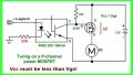
I assume a 12vdc battery driving a linear actuator (gear motor and allthread) based on a signal a photovoltaic transistor would soon cook the transistor and wondered if the little 12vdc relays I had used before plus a 100ohm resistor (I think) on the transistor would protect it. I assume the motor will pull 8 amps or about 100watts max. Is there a better more durable or solid state power switch than those relays and does 100ohm sound like the right size?
 

KeithWalker

Joined Jul 10, 2017
3,603
Are you looking for a complete module or do you plan on building one? If you are building one, then you should use a power MOS FETs, e.g. IRFZ44. I would recommend at least two connected in parallel, mounted on a heat sink, to switch that motor.
 

MisterBill2

Joined Jan 23, 2018
27,164
Can you provide us with information on that " signal a photovoltaic transistor ", which will help to avoid a lot of guessing about how to use it in a control arrangement. Also, explaining what the control should do as far as controlling that " (gear motor and allthread)" system will be useful in devising a correct control scheme.
My skills at knowing what others have in mind are quite poor, is the reason I am asking for details.
 

Thread Starter

YankeePirate

Joined Dec 10, 2024
64
Are you looking for a complete module or do you plan on building one? If you are building one, then you should use a power MOS FETs, e.g. IRFZ44. I would recommend at least two connected in parallel, mounted on a heat sink, to switch that motor.
MOSFET: Thank you. Never wired one (just relays) so I assume transistor signal splits to feed a 3 leg 12vdc in & out and MOSFET trigger? Will research. And if I want it to never die use 3+? Keep adding them until none are warm? Its intermittent, pulsing every 3-5 seconds for 1-2 seconds ON, 3-5 seconds off.

SIGNAL: Smartphone screen black or white.
Embedding phototrans in circular velcro/stretchy band, slide over phone, align over flashing black/white square.

ESP: Reading someone's mind is always a challenge until their 3rd cuervo.
 

Thread Starter

YankeePirate

Joined Dec 10, 2024
64
I found this circuit which is close. But final version driving a reversible gear motor requires two photovoltaic circuits: one forward, one reverse. My inclination is to add diodes somewhere to prevent backfeeding off circuit.
 

Attachments

Thread Starter

YankeePirate

Joined Dec 10, 2024
64
NEWBIE QUESTION: How do I provide 5vdc to transistor from 12vdc battery? I assume adding a ?2-3 ohm resistor to 12VDC should drop voltage to 5?
 

MisterBill2

Joined Jan 23, 2018
27,164
NEWBIE QUESTION: How do I provide 5vdc to transistor from 12vdc battery? I assume adding a ?2-3 ohm resistor to 12VDC should drop voltage to 5?
To get a steady 5 volts for that opto device use a regulator like the LM78M05, which is good for 100mA, which I am guessing is less than the current draw of that opto-isolator
 

Thread Starter

YankeePirate

Joined Dec 10, 2024
64
To get a steady 5 volts for that opto device use a regulator like the LM78M05, which is good for 100mA, which I am guessing is less than the current draw of that opto-isolator
Thank you. A $0.40 cent solution. I thought just frontloading a resistor would work (what I used back in 1983 with regular transistors) but a regulated 5VDC seems wiser.
 

MisterBill2

Joined Jan 23, 2018
27,164
Certainly a resistor can provide a voltage drop. But ohms law warns us that the voltage drop depends on the current. A rather brutal limitation.
 

Thread Starter

YankeePirate

Joined Dec 10, 2024
64
Sadly trying to click save image or get a high res screenahot failed and I am blind in one eye so I have to Zoom everything but it appears to be a circuit for ?forward/reverse a motor? I hope so. Today I started by buying 200W MOSFETS, 2.types of 5vdc regulators, one chip has 3 legs, the other is a chip with a bunch and no pin out diagram. It looks like I need some resistors and I have a.bucket around here with assorted parts. Got breadboards and will try to cobble a.fwd/rev circuit based on various diagrams recvd so far. Thank you all.
 

Thread Starter

YankeePirate

Joined Dec 10, 2024
64
Hi LowQ

Managed to find these examples and started buying parts and hope this clarifies the objectives. A couple of questions;
1. Any idea what range R1 might be?
2. Would MOSFETs allow ample current?
3. Might they replace BD140s?
4. Upper and lower horizontal lines around motors were not marked + / - and I wondered if upper was +12vdc and lower was ground?
5. It says A&B must never both be high so I wondered how to add protection so if A is high, B is disabled.
Also your circuit shows Optoisolators and the triggers are light-based - top circuit. Not sure if that was confusing.
Thank you and Happy Nude Year; now go run naked in a forest at least once in 2025. No selfie required thank you.
 

Attachments

LowQCab

Joined Nov 6, 2012
5,101
You shouldn't start buying parts until You are quite sure that your project is likely to work.

You are asking questions that lead me to the conclusion that
You don't really understand how and why any of these Circuits work.

Lets start over.

What is your Power-Supply ? details are necessary.

What are the Specifications of your Motor ? details are necessary.

What is your Motor attached to ? details are necessary.

Pictures and Manufacturers-Specification-Sheets would be a huge bonus.
.
.
.
 

Thread Starter

YankeePirate

Joined Dec 10, 2024
64
Thank you for prompt reply. Despite building basic robotics 40 years ago with relays, transistors, diodes and resistors, I am a complete newbie.

To answer your questions,
power is 200ah 12vdc LiFePo boat batteries charged by solar and diesel gen.

12vdc Motor is linear actuator shown here and likely to get upgraded (more amps/better duty cycle):.Manual says 3amps. Others I saw said 8amps so I am aiming for 10.

Duty cycle.anticipated to be 1-2 seconds on, off 2-5 seconds, repeat for hours


https://www.amazon.com/dp/B0D72HDBG...XRhaWwp13NParams#immersive-view_1735851776338
 
Last edited:

LowQCab

Joined Nov 6, 2012
5,101
OK, your Actuator is unusual in that it provides slightly more information than most Chinese stuff,
but still doesn't provide any Current-Specifications,
so your project will just have to be built with some substantial over-kill in the Power-Section,
or You could simply use 3-Automotive "Bosch-Style" 5-Pin-Cube-Relays.

You've stated that You want "Photo-Voltaic-Switching", this is were things might start getting tricky.

First, You must realize that there must be 2 Photo-Resistors or Photo-Transistors,
and that there must be a careful balancing-act between sensitivity to your remote,
and the level of ambient-light, and/or, Sunlight.

It may be a better idea to use a generic Key-Fob type Remote-Control-Switch,
they're reasonably cheap, but I personally don't know if they are available with 2-Buttons,
they should be, but I'm not willing to spend as long as it may take to find them,
especially if this doesn't match-up with what You want.
Perhaps someone else here already knows about the availability of these,
or is willing to do an extensive search after You give your approval.

As many details as possible are always needed.
.
.
.
 

Thread Starter

YankeePirate

Joined Dec 10, 2024
64
Motor manual in box says 3.amps. I.anticipate 5-8amps.with a more.robust unit or.10 max.

Photo transistors I bought will be inserted.into a band i.e. stretchy wrist band that slips over a phone screen so if left half (third) of screen is light bright white signal A gets triggered and if right.side (third) is.light/white.signal.B is triggered (reverse motor) or all black equals no signal no motor. Center 1/3 will always be dark to prevent cross triggering/light bleed

Hope.that helps.
 

LowQCab

Joined Nov 6, 2012
5,101
I know of no practical device that can determine which half of the Phone's Screen is covered or exposed.

Is this the specific reason that You created this Thread ?
.
.
.
 

MisterBill2

Joined Jan 23, 2018
27,164
Really, the sensing could be done using the photo-voltaic solar cells that have been around for over 50 years. Those flat-plate cells generate a bit of voltage when illuminated. Of course there will be some amplification required, but that is the easy part. Getting the phone to display such a screen will be the challenge part.
I see that this scheme will allow remote control in a non-tracable, non-jamable manner from a non-trackable transmitter anywhere in the world, almost. Quite interesting indeed. Somebody could pilot a drone of fair size, or even a twin-engine plane, from anywhere. The feedback could be from another phone camera inside the plane, looking out.
Very interesting indeed.
 

Thread Starter

YankeePirate

Joined Dec 10, 2024
64
Really, the sensing could be done using the photo-voltaic solar cells that have been around for over 50 years. Those flat-plate cells generate a bit of voltage when illuminated. Of course there will be some amplification required, but that is the easy part. Getting the phone to display such a screen will be the challenge part.
I see that this scheme will allow remote control in a non-tracable, non-jamable manner from a non-trackable transmitter anywhere in the world, almost. Quite interesting indeed. Somebody could pilot a drone of fair size, or even a twin-engine plane, from anywhere. The feedback could be from another phone camera inside the plane, looking out.
Very interesting indeed.
A friend at anchor spent several hours debugging his autopilot while I sipped a beer and nagged "Dead unit. I could write software to steer your sailboat with any smartphone and an actuator & a circuit to read a screen white or dark" and I did write the software. Left/right white/black navigation driven control is done.

Meanwhile, to cable it up I'm using a std USB 15 foot plus a Y so the phone can charge at the same time and intend to use the 2 data lines in the cable to send a 5 volt signal from phone band to actuator; fwd or reverse or off.

Just need a circuit where a tiny solar/photo transistor sends a 5 volt signal to go down to a circuit at the actuator which controls 12v motor or phototransistor allows a 5vdc ground or reverses 5vdc polarity; all signals I can handle with USB cable.
 
Top