 Facebook
 Google
 GitHub
 Linkedin
Hi All,
I'm currently trying my hand at creating a device I can use in a loud vehicle to communicate internally with the driver/co-driver, or externally via a UHF radio. My inspiration is pretty much the kind of intercoms that helicopters use. Pilot/Co-pilot have headsets that they can talk to eachother with, as well as to others via a radio. But after a few goes at it, it's clear there are many large gaps in my knowledge, and I don't know what I don't know... So I thought I would ask here to at least confirm I'm somewhere near the correct track.
The main parts I'm struggling with is handling the audio signals. I've had experience before with microcontrollers, digital circuits, and programming. But the audio/analog stuff is doing my head in. It's my first time dealing with op-amps and my lack of an actual education on the subject is showing.
I'll focus on the two parts I think I'm having the most trouble with, because I think if I solve those then I can figure the rest out from that solution.
The design is as I think you'd expect; The two drivers have a headset each. When a driver presses the intercom button, their voice is heard in both headsets. The headsets are essentially some earmuffs with speakers in them, and an electret boom mic.
The signal from the electret is tiny, so presumably I need some kind of pre-amplifier to get it to line level (Correct term? About 1v p-p?). My current design revolves around using LM380 power amps for both the electret pre-amp and the headphone output amp. I think this was a mistake but I'm not really sure why. The audio I get out is pretty badly clipped by the time it is loud enough to hear over the vehicle. And the background noise is very noticeable, so ideally I'd like less gain but more volume. I don't know if 'gain' in an op-amp sense is the same as 'gain' from like an audio mixing desk.

So that's my first issue. Audio out of this circuit is seemingly clipping and not-great and I'm not sure why, other than 'This probably isn't what lm380 is for' pretty much. Half the reason I picked it was to avoid another BoM item, and it was readily available from down the road in DIP...
I spied a TI reference design TIPD181 reference design | TI.com (Single-Supply, Electret Microphone Pre-Amplifier) in my travels that I think I will remorselessly plagiarise in the next design.
Other questions on this circuit include:
- Why 10k on the output? Is this an impedance thing? What is impedance in the case of audio signals? The same?
- Do the types of capacitor matter? As in tant vs al-ellectro vs poly, but also as in polarised vs non-polarised.
- Do the values of the capacitors on the input and output really matter? Or are they just there to stop signals going backwards or something? iunno.
- Should volume control be done on the input signal, or as a function of gain on the op-amp?
- The reference design uses the op-amp as a 'transimpedance amplifier' vs whatever the lm380 is doing. What is the significance of that?
The second issue I think I'm having is merging all the different audio signals into one signal that then gets amplified out to the headsets.
In addition to the intercom circuit, there is also the ability to plug in a UHF radio, as well as a music source via 3.5mm jack. So we end up with essentially four individual line-level (hopefully) signals that need to be merged into one and then shot off to each headset's output amplifier. I came across the circuit for a 'summing amplifier' which looked like it would do that task, based on a tl071 op-amp.

But the audio coming out of it was hot garbage. It functioned better without the amp in place, so the signals just essentially went through a few resistors.
The purpose of the amp was to limit an issue in a previous version of the design where the volume in the headset would change depending on if anyone was using the intercom, if the music was playing, or if the UHF was receiving. Like if you had music playing and then used the intercom, the volume of both would be about half. And then half again if the UHF chimed in. This circuit was supposed to buffer the signals I think so that didn't happen. And sure enough it didn't happen, but the clipping was much worse with the IC in the socket. The overall output volume was about the same, though. Which I think proves the gain as indeed 1x? I ended up removing it as I mentioned previously, and the volume sag as more channels chimed in was notably less but not entirely eliminated.
So:
- I can't remember why I chose this op-amp as the adder. It was probably available down the road as well in DIP... Does it look correct? Is the concept at least in the ballpark or is there a better solution for this? I think it at least had a good enough slew rate to do audio signals at a 1x gain.
In addition to all that rubbish, there was also this other issue I couldn't explain/diagnose.
There are volume pots on the input to the pre-amps, as well as on the input of the output amplifier (The pre-amp and output amp circuits are identical, except the output amp doesn't have the PTT circuit). In certain combinations of knob orientation (Usually to the high or low extremes), there is incredibly bad interference. High pitch buzzing and whining, and the power consumption of the lm380s would plateau or even start to go down as volume was increased. These pots are linear, so I can only assume that if I change them to the log pots that they should be, that I'll end up with only a very narrow band of 'usable' volumes. I originally thought it was some picked up interference from the breadboard pins, but even after getting a PCB made, the issue was almost identical.
- Any hints as to what may be causing this, or what I can do to narrow the cause down? Is it just interference between the op-amps? Or some critical design mistake I made? Is there a way to make it not do this?
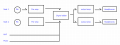
In the end, the block diagram looks something like this:

Would you recommend any way I could do this better? Is there critical concept I'm missing that could help me work through these issues or build the circuit better?
Thank you so much for making it all the way to the end. This post ended up a lot longer than I was anticipating, and it got a bit rambly. I realise it's a lot to ask of internet strangers to freely spend so much time potentially solving for my inadequacies, so any help or advice is very greatly appreciated.
Many Thanks, Tangence.
I'm currently trying my hand at creating a device I can use in a loud vehicle to communicate internally with the driver/co-driver, or externally via a UHF radio. My inspiration is pretty much the kind of intercoms that helicopters use. Pilot/Co-pilot have headsets that they can talk to eachother with, as well as to others via a radio. But after a few goes at it, it's clear there are many large gaps in my knowledge, and I don't know what I don't know... So I thought I would ask here to at least confirm I'm somewhere near the correct track.
The main parts I'm struggling with is handling the audio signals. I've had experience before with microcontrollers, digital circuits, and programming. But the audio/analog stuff is doing my head in. It's my first time dealing with op-amps and my lack of an actual education on the subject is showing.
I'll focus on the two parts I think I'm having the most trouble with, because I think if I solve those then I can figure the rest out from that solution.
The design is as I think you'd expect; The two drivers have a headset each. When a driver presses the intercom button, their voice is heard in both headsets. The headsets are essentially some earmuffs with speakers in them, and an electret boom mic.
The signal from the electret is tiny, so presumably I need some kind of pre-amplifier to get it to line level (Correct term? About 1v p-p?). My current design revolves around using LM380 power amps for both the electret pre-amp and the headphone output amp. I think this was a mistake but I'm not really sure why. The audio I get out is pretty badly clipped by the time it is loud enough to hear over the vehicle. And the background noise is very noticeable, so ideally I'd like less gain but more volume. I don't know if 'gain' in an op-amp sense is the same as 'gain' from like an audio mixing desk.
So that's my first issue. Audio out of this circuit is seemingly clipping and not-great and I'm not sure why, other than 'This probably isn't what lm380 is for' pretty much. Half the reason I picked it was to avoid another BoM item, and it was readily available from down the road in DIP...
I spied a TI reference design TIPD181 reference design | TI.com (Single-Supply, Electret Microphone Pre-Amplifier) in my travels that I think I will remorselessly plagiarise in the next design.
Other questions on this circuit include:
- Why 10k on the output? Is this an impedance thing? What is impedance in the case of audio signals? The same?
- Do the types of capacitor matter? As in tant vs al-ellectro vs poly, but also as in polarised vs non-polarised.
- Do the values of the capacitors on the input and output really matter? Or are they just there to stop signals going backwards or something? iunno.
- Should volume control be done on the input signal, or as a function of gain on the op-amp?
- The reference design uses the op-amp as a 'transimpedance amplifier' vs whatever the lm380 is doing. What is the significance of that?
The second issue I think I'm having is merging all the different audio signals into one signal that then gets amplified out to the headsets.
In addition to the intercom circuit, there is also the ability to plug in a UHF radio, as well as a music source via 3.5mm jack. So we end up with essentially four individual line-level (hopefully) signals that need to be merged into one and then shot off to each headset's output amplifier. I came across the circuit for a 'summing amplifier' which looked like it would do that task, based on a tl071 op-amp.
But the audio coming out of it was hot garbage. It functioned better without the amp in place, so the signals just essentially went through a few resistors.
The purpose of the amp was to limit an issue in a previous version of the design where the volume in the headset would change depending on if anyone was using the intercom, if the music was playing, or if the UHF was receiving. Like if you had music playing and then used the intercom, the volume of both would be about half. And then half again if the UHF chimed in. This circuit was supposed to buffer the signals I think so that didn't happen. And sure enough it didn't happen, but the clipping was much worse with the IC in the socket. The overall output volume was about the same, though. Which I think proves the gain as indeed 1x? I ended up removing it as I mentioned previously, and the volume sag as more channels chimed in was notably less but not entirely eliminated.
So:
- I can't remember why I chose this op-amp as the adder. It was probably available down the road as well in DIP... Does it look correct? Is the concept at least in the ballpark or is there a better solution for this? I think it at least had a good enough slew rate to do audio signals at a 1x gain.
In addition to all that rubbish, there was also this other issue I couldn't explain/diagnose.
There are volume pots on the input to the pre-amps, as well as on the input of the output amplifier (The pre-amp and output amp circuits are identical, except the output amp doesn't have the PTT circuit). In certain combinations of knob orientation (Usually to the high or low extremes), there is incredibly bad interference. High pitch buzzing and whining, and the power consumption of the lm380s would plateau or even start to go down as volume was increased. These pots are linear, so I can only assume that if I change them to the log pots that they should be, that I'll end up with only a very narrow band of 'usable' volumes. I originally thought it was some picked up interference from the breadboard pins, but even after getting a PCB made, the issue was almost identical.
- Any hints as to what may be causing this, or what I can do to narrow the cause down? Is it just interference between the op-amps? Or some critical design mistake I made? Is there a way to make it not do this?
In the end, the block diagram looks something like this:
Would you recommend any way I could do this better? Is there critical concept I'm missing that could help me work through these issues or build the circuit better?
Thank you so much for making it all the way to the end. This post ended up a lot longer than I was anticipating, and it got a bit rambly. I realise it's a lot to ask of internet strangers to freely spend so much time potentially solving for my inadequacies, so any help or advice is very greatly appreciated.
Many Thanks, Tangence.
Attachments
-
 53.8 KB Views: 0


