Just want to sanity check the protections I put in place for an Arduino INPUT pin.

Thread Starter

Jassper

Joined Sep 24, 2008
103
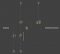
R1 Pullup - keeps Node X HIGH when not pulled LOW
C1 Should help with filtering and debounce
D1 should help with ESD/Hot swap
R2 limit current
D2 Should clamp the Arduino pin to 5v

The Arduino Input pin is looking for a momentary ground.
NODE_X could be connected to another device providing a momentary ground from another MPU GPIO pin or it could come from a mechanical momentary switch connected to ground.

Basic protections, not expecting anything drastic but 12v could be accidentally applied to NODE_X, but not likely.
I'm most concerned about the device at NODE_X being connected/disconnected without powering down the system.

Thanks for any input.
Screenshot 2026-04-12 094702.png
 

Attachments

Last edited by a moderator:
Generally, with digital inputs you design for short to gnd, short to system power, open, ESD events. Any of which causes no damage.
What you have will not work great. SZSMF5.0AT1G breakdown at 7V/10mA and clamps hard at 10V.
So it will smoke if 12V is ever applied to the input. Better to put it after a resistor so that it can take the system voltage say 12V forever.
D2 is 1/2 wasted, use it to clamp to both GND and +5V. Although some MCU are fine if you use their internal diodes for this and limit pin injection current as it is called. It does depend on the MCU what you can get away with.
I'll look for my schematic that I use and post it when I find it.
 

Ian0

Joined Aug 7, 2020
13,103
Be careful about D2. Think about what happens if a fault current flows. It ends up in the power supply. If the fault current is greater than the load current on the power supply, the regulator will no longer be able to control it, and the power supply voltage increases, maybe to the point it can destroy all the logic on the 5V supply.

Leave out D2 and place D1 AFTER the current limiting resistor for the reasons stated by @prairiemystic
 

BobTPH

Joined Jun 5, 2013
11,479
A resistor in series to limit current is all that is typically needed because the internal clamp diodes can then keep voltage safe.
 
This is a complicated topic and everyone has their preferred approach - many are theoretical, from the armchair.
So many poor Arduino's getting zapped lol.

As mentioned, using a TVS is good but that fails if DC overloads can occur. Then you need two level protection and more parts.

This is a low cost approach to consider. Used in automotive and passes the tests, BCI included. But it relies on the MCU being tough, which is the norm for automotive ECU's and not for many others.

DI protection 2026.PNGC1 typically 10-47nF 200V and greatly lowers ESD by capacitive voltage division (see Kemet graph) plus it also shunts RF by tuning it quite low, if your field wiring is long making a good antenna. So AM radio, WiFi, cellphone etc. cannot start a resonance there. I use 33nF, you are down to around 250V for ESD hits.
Kemet_ESD graph.PNG


R1 pullup is to either system (say 12V) power or MCU (5V) power and sets the contact wetting current. You need a mA or two at least.
R2 is typically 33k-100k and limits MCU injection current for when transients say ESD (250V) or long term 12-24V happen. Sustained use add another divider resistor (after R2) to bring it down to 5V max.
If the MCU has a weak injection current rating, most are rated around ±1-2mA, the extra diode clamp D1 protects for that, and dumping +ve overload to the rail when the MCU is powered off ATmega328P is rated 5mA for that and pin ±1mA injection current when it's normally powered.

C2 does the last RC filtering typically 33nF/47k gives around 85Hz/1.9msec

I guess it really depends on how robust you want your project, the environment and clown wiring mistakes that can happen. Also how much PCB room you have, cost.
 

joeyd999

Joined Jun 6, 2011
6,223
For switched inputs, I prefer PN junction protected contact-closure inputs as disclosed here. All debounce I do in code.
 
Last edited:

Ian0

Joined Aug 7, 2020
13,103
For switched inputs, I prefer PN junction protected contact-closure inputs as disclosed here. All debounce I do in code.
Robust, yes, but you have lost 80% of your noise immunity. It was 2.5V and now it's 0.5V.
It will be fine provided each switch is wired to the circuit board with its own pair of wires, but if some panel wirer decides to take the 0V from the PSU visiting each switch in turn and eventually reaching the control board connecting up anything else that needs a 0V connection on the way, then it might be in trouble.
 

Ian0

Joined Aug 7, 2020
13,103
Have done. That's why I know about the panel wirers!
Now I connect the switches to 24V, and divide the voltage down on the pcb. The voltage divider provides all the protection the MPU needs, it also provides enough switch current to keep silver oxide switch contacts wetted.
 

Thread Starter

Jassper

Joined Sep 24, 2008
103
Thanks everyone for suggestions - it gaves me a few things to consider.
After I posted I did think that D1 might fry without a limit resistor - so Moving it to the other side of R2 makes sense.
If the internals can handle any over voltage, then I don't need D2. If I am understanding correctly. I did consider what happens to the over voltage if D2 conducts but hearing someone else mention it confirms my thoughts.
 
Top