Sanity check of a schematic

Thread Starter

metermannd

Joined Oct 25, 2020
472
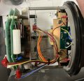
As mentioned before, I've been gathering what information I can of a system that used the electric distribution system as a communications medium, and I recently had the opportunity to examine a transponder used with this system.

Most of these are modified meters where a reflective sensor acts on a painted mark on the meter's disk so the transponder logic can calculate the amount and rate of energy usage (I have one of this style). The transponder I got to examine was a style where three leads (marked K, Y, and Z) extend from its socket to a meter with an external 'pulse initiator' that alternately completes the circuit between Y / K and Z / K based on the disk's rotation.

Unfortunately, there was no screwdriver at hand within the office to allow disassembly of the board tower, so I had to make do with trying to get as many different photo angles as I could of the pulse input board (and even so, I missed a couple crucial views).

From those pictures I assembled the schematic below, and even so, I had to make a few educated guesses for now (I may have a chance to acquire this transponder at some point as this utility abandoned its demand response system years ago).

The only parts I have not been able to confirm were the D5 / D6 cathode connections and Pin 1 on both optoisolators. They seem to go to +5 but I cannot be 100% positive. The PWR_FLAG nodes are just there for KiCAD's 'electrical rules check' proofreader.
 

Attachments

Last edited:

drjohsmith

Joined Dec 13, 2021
1,579
you mention the electrical distribution system for communication, and also using the rotating power usage disc,
these are not the same, and worrying , seems to indicate your playing with mains electricity at the ppwer companies meter , which is illegal,

there are systems to communicate over the mains wiring, the classic is the X11 standard.
these do not require you to modify, un screw or otherwise interfear with the mains meter

older meteres have a rotating disc, with a mark on it, that can be detected by an external optical sensor , to count 100w per rev.

New ones , have a led that flashes every 100 watts,
for high load feels like on constantly.

again neither of these need you to access the meter
 

Thread Starter

metermannd

Joined Oct 25, 2020
472
I am fully aware of the dangers of handling mains-level electricity and of the implications of the metering infrastructure. I have no interest in nor intent of breaching either barrier (although I have worked for a contractor in the past that provided on-site maintenance and testing of electric meters).

There are four different systems I am aware of that used the power lines as a means to convey information between the utility and the customer's premises - Ripple, TWACS, Hunt Technologies, and Westinghouse's Distribution Line Carrier system. One is strictly for demand response, two are advanced metering platforms, and one is used for both.

Given the increasing availability of wireless communications, it seems that powerline carrier systems are being phased out (I am aware of one company that retired its powerline carrier system in favor of wireless due to interference from VFDs).

I also had involvement on the manufacturing side of one of these systems and found it sufficiently interesting to make an attempt to preserve whatever information I can find on the earlier components used with that system, given that the company that handled support had long since discarded information on these earlier components. Also, they recently ended official support for that powerline carrier system as many of their customers are migrating to wireless systems instead.

Again, my main goal was and continued to be to document the answer to "how did this system work?"

That is all.
 

drjohsmith

Joined Dec 13, 2021
1,579
I am fully aware of the dangers of handling mains-level electricity and of the implications of the metering infrastructure. I have no interest in nor intent of breaching either barrier (although I have worked for a contractor in the past that provided on-site maintenance and testing of electric meters).

There are four different systems I am aware of that used the power lines as a means to convey information between the utility and the customer's premises - Ripple, TWACS, Hunt Technologies, and Westinghouse's Distribution Line Carrier system. One is strictly for demand response, two are advanced metering platforms, and one is used for both.

Given the increasing availability of wireless communications, it seems that powerline carrier systems are being phased out (I am aware of one company that retired its powerline carrier system in favor of wireless due to interference from VFDs).

I also had involvement on the manufacturing side of one of these systems and found it sufficiently interesting to make an attempt to preserve whatever information I can find on the earlier components used with that system, given that the company that handled support had long since discarded information on these earlier components. Also, they recently ended official support for that powerline carrier system as many of their customers are migrating to wireless systems instead.

Again, my main goal was and continued to be to document the answer to "how did this system work?"

That is all.
Ta for that.

I was assuming you meant the X11 type power line control.
We've had others that want to hack the meteres, and when you mentioned about the the rotating wheel in the meter ..

Anyway , are these systems such as M carrier system not already well documented ?
 

drjohsmith

Joined Dec 13, 2021
1,579
Is that 100w-hr or 100w-min?
Utility meters count energy not power.
interesting,

if I use 1 kW for one hour , or 100w for 10 hours , the meter shows 1 Kwh ,

as you say , the meter reads in Watt hours , the disc revolves or the led flashes for each 100 Wh , 10 times for a Kwh

my apologies for not putting the h on the units ,
 

MisterBill2

Joined Jan 23, 2018
27,323
The system, as shown in the PDF of post #1, does not work, because the meter is switching on and off five volts the the opto isolators already biases with five volts. If, how ever, a "ground" connection is made , then a pulse will be sensed by that device connected to J3
 

Thread Starter

metermannd

Joined Oct 25, 2020
472
MrBill: That's what I was wondering, and why I asked.

Another possibility is that pin 1 on the optos are actually tied to ground?
 

MisterBill2

Joined Jan 23, 2018
27,323
MrBill: That's what I was wondering, and why I asked.

Another possibility is that pin 1 on the optos are actually tied to ground?
Not possible if the opto circuit shown is correct!Pin#1is the positive source for the opto LED, Pin #2 is the DC return(negative) for the LED current. But if the signal is produced by an NPN open collector then it can function.
 

Thread Starter

metermannd

Joined Oct 25, 2020
472
The output of this board plugs into J5 on the MCT main board attached below.
(I still need to review and fix the arrow directions on the signals)
 

Attachments

Thread Starter

metermannd

Joined Oct 25, 2020
472
AK: You're right. Thank you for that correction.
Looking again at the pictures, I don't see anything that suggests pin 4 on U1 / U2 are tied to anything except P3 pin 3.

Now I just need to resolve pin 1 on the optos and I should be set.

Here's one of the pictures I took of this unit. The MCT main board is at the top, then the analog (P/S + transmitter) board, and finally, the pulse board this thread is about. So you can see the difficulty of getting a clean view without a screwdriver to disassemble the board tower.
 

Attachments

Thread Starter

metermannd

Joined Oct 25, 2020
472
Is that 100w-hr or 100w-min?
Utility meters count energy not power.
Actually, look for a number Kh on the meter's nameplate (and if electromechanical, look for the Rr marking too). That's the number of watthours per disk revolution (or equivalent). On electromechanical meters, the register ratio x reduction ratio (between the disk spindle and register pickup, normally 100:1 for residential meters) x Kh should equal 10,000 or 10kWh.
 

Thread Starter

metermannd

Joined Oct 25, 2020
472
So I should try again to follow the trace from pin 1; the other possibility is that the trace swings towards VR1 input instead.
 

AnalogKid

Joined Aug 1, 2013
12,088
It looks like the max possible current is around 40 mA, for an approx worst case ripple voltage across C1 of 3.4 V. What is the RMS value of the supply voltage at P1?

ak
 

Thread Starter

metermannd

Joined Oct 25, 2020
472
I don't have that info at hand, but this is a relatively low-current unit.
The main P/S winding (blue leads) is 11VAC, 300mA and the transmitter P/S winding (gray leads) is 35VAC, 250mA.
Based on my notes, I assume the orange / orange-white leads (accessory power) are very likely 22VAC, 150mA.
I would tend to assume that the yellow leads powering this circuit would be a second 11VAC winding?
 

Baker Steve

Joined Feb 21, 2016
29
The post #1 schematic has the same GND on both sides of the opto-couplers.

Also, it's X10, not X11; still alive and well.

ak
Alive, maybe – well, I'm not so sure. It's given me a lot of problems over the years, and the kit is so long out of manufacture that reliability is low. As a result I'm gradually migrating my systems to ZWave.
 
Top