Facebook
 Google
 GitHub
 Linkedin
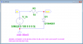
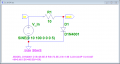
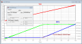
Do you know how to calculate the power that will be dissipated in the resistor and the diode for a given supply voltage? Do you know what the power ratings are for the resistor and the diode? If so, then you have the proper knowledge and can back up your concern with an appropriate calculation to justify that concern. If you haven't gotten far enough to know about power dissipation in components, then you don't have the proper knowledge yet and have to go on blind faith for now.
[S.T. 2] - Semester task 2
- Thread starter PsySc0rpi0n
- Start date