Facebook
 Google
 GitHub
 Linkedin
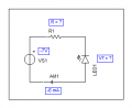
But how are you going to see the behavior of the zener? When the zener is reverse biased, the LED is forward biased, right? So the LED is going to clamp the voltage at around 2V (whatever the LED forward voltage is).I can't see the problem you're referring to. I have placed the zener in the opposite direction of the LED having in mind that to make the LED work, zener should be reverse biased!
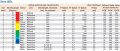
The LED's Breakdown Voltage is 5V and the Zener's is 6V2.
What our teacher is asking is to purpose a circuit to make a LED light on using a Zener and get the characteristic curves for both the Zener and LED. So I suppose he only wants the plot of these curves when the LED is ON (Zener in reverse bias mode and LED e direct bias mode simultaneously).
[S.T. 2] - Semester task 2
- Thread starter PsySc0rpi0n
- Start date


")