 Facebook
 Google
 GitHub
 Linkedin
hi,
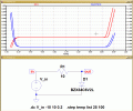
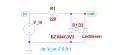
The LTS temp is the ambient temperature of the 'circuit plot'
The diode is passing current and so it generates heat which raise its body temperature above the 100C ambient.
Look at the self heating dissipation of the diode in this image
EDIT:
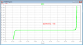
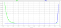
Look at this modified Sim of the diode self heating at a fixed 25C temp ambient, its dissipating 1 Watt.! as the current increases.
The LTS temp is the ambient temperature of the 'circuit plot'
The diode is passing current and so it generates heat which raise its body temperature above the 100C ambient.
Look at the self heating dissipation of the diode in this image
EDIT:
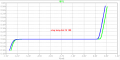
Look at this modified Sim of the diode self heating at a fixed 25C temp ambient, its dissipating 1 Watt.! as the current increases.
Attachments
-
 34.3 KB Views: 23
 -
 30.2 KB Views: 22
Last edited:


")


