[S.T. 2] - Semester task 2

Thread Starter

PsySc0rpi0n

Joined Mar 4, 2014
1,773
Well, this next task is about diodes and zeners.

I might have some difficulties in spelling the technical terms in English, so please bear with me a little.

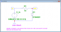
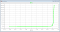
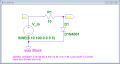
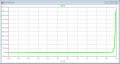
Our teacher is asking us to plot the characteristic curve of a 1N4001 diode.
Is it possible to invert the data plotted in each axis??? I mean plot I(D1) in Y-axis and V(out) in X-axis???

I would like to see something like we see in the datasheets instead of the curve going right as in the attached images.
 

Attachments

Last edited:

Thread Starter

PsySc0rpi0n

Joined Mar 4, 2014
1,773
hi Psy,
If you need to plot the 1N4001 diode VI curve, what is is the 220R resistor doing in the circuit.?

E
Hi Mr. Ericibbs. Long time no see...
Glad to see you here!

Well, the resistor is there because it's the circuit our teacher has purposed us to simulate to get the diode characteristic curve!
Isn't that resistor polarizing the diode?Reverse or direct polarization?
 

Thread Starter

PsySc0rpi0n

Joined Mar 4, 2014
1,773
I surely believe that your options are better than any exercise any teacher can give us, but that was the circuit we were given to simulate.

The only reason to not use a resistor is to avoid limiting circuits current? Is you example applicable in real situation? Isn't there the risk of blowing/burning the diode with that much current as 2A???

If we can do that in school's labs, I'll use your simulation without the resistor! We can't burn/blow components in labs or we will not be able to graduate at this class!
 

ericgibbs

Joined Jan 29, 2010
18,872
hi,
If I had to plot an actual diode VI curve I would first read the datasheet in order to determine the maximum continuous specified current for the diode.
Which is approx 1 Amp for a 1N4001.
So I would set the bench power supply output current limit to 1.1Amps and the starting voltage of the power supply at 0V
Using a DVM I would measure the Vfwd of the diode at measured increments of power supply output current, then plot the result.

E
 

Thread Starter

PsySc0rpi0n

Joined Mar 4, 2014
1,773
So, would it be the same as using a resistor to limit the current to 1.1A and simulate on LTSpice to get the curve???

And how do you switch the axis data from XX to YY? I mean to have current in YY and voltage output in XX axis???
 

ericgibbs

Joined Jan 29, 2010
18,872
You could select a series resistor that limited the diode current to say 1.1A.

A 10R with a 0 to 12V supply would be close enough.
Check the resistors wattage requirement.!
 

Thread Starter

PsySc0rpi0n

Joined Mar 4, 2014
1,773
You could select a series resistor that limited the diode current to say 1.1A.

A 10R with a 0 to 12V supply would be close enough.
Check the resistors wattage requirement.!
Ok, and what about to switch the XX and YY axis data? I(D1) to YY and V(out) to XX axis?


Edited;
I got it!
 
Last edited:

Thread Starter

PsySc0rpi0n

Joined Mar 4, 2014
1,773
Ok, here's how I did the two 1st simulations... I'll argument that for simulation purposes I've used a small limitation resistor calculated to limit the circuit's current to the maximum that the diode can handle (specs given by datasheet).


Now, I have to do the same but for a sine waveform for V_in with a magnitude of 5V and 10V and a frequency of 100Hz in two separate simulations.

But he's asking for a V_out plot and then he asks if we can get the "transfer curve" in these conditions... Is this "transfer curve" the same as the "characteristic curve"?
 

Attachments

Last edited:

WBahn

Joined Mar 31, 2012
30,082
Hi Mr. Ericibbs. Long time no see...
Glad to see you here!

Well, the resistor is there because it's the circuit our teacher has purposed us to simulate to get the diode characteristic curve!
Isn't that resistor polarizing the diode?Reverse or direct polarization?
The resistor has no effect on the polarization (not really the best term to use, but I'm assuming you mean whether the diode is forward biased or reverse biased) of the diode. It is limiting the current in the diode because otherwise you would have extremely high currents. Since this is a simulation, remove the resistor and see what the sim says the current would need to be in order to sustain 12V of forward bias across it.

In a physical set up, getting a good read of the voltage across and current through a diode directly can be challenging. But if you use a large voltage supply and a suitably sized resistor whose value is well known, then you can get a good reading for the current by measuring the voltage across the resistor and using Ohm's Law.
 

Thread Starter

PsySc0rpi0n

Joined Mar 4, 2014
1,773
The resistor has no effect on the polarization (not really the best term to use, but I'm assuming you mean whether the diode is forward biased or reverse biased) of the diode. It is limiting the current in the diode because otherwise you would have extremely high currents. Since this is a simulation, remove the resistor and see what the sim says the current would need to be in order to sustain 12V of forward bias across it.

In a physical set up, getting a good read of the voltage across and current through a diode directly can be challenging. But if you use a large voltage supply and a suitably sized resistor whose value is well known, then you can get a good reading for the current by measuring the voltage across the resistor and using Ohm's Law.
Ok, I'm just going to use a 9 ohm resistor like Mr. EricGibbs said to limit current to around 1.1A which is what datasheet says.
I would like to know why would the teacher placed a resistor there. I need to know how to argument if he asks me why did I removed/changed the resistor in the exercise!

That's just wrong! :D
The best way to learn electronics is to burn your fingers now and then and to let the magic smoke out of components from time to time.
I understand that but our school and all country itself is in "low budget," or better "zero budget" mode, so there's no money for new material for labs... Last semester me and some colleagues of mine had a conversation (after class) with one teacher of ours and he was kinda desperate because there's no conditions to teach what they are supposed to teach and he said he would rather close schools than to teach in extremely poor conditions.

Anyway, let's get back to ON TOPIC again!
 

WBahn

Joined Mar 31, 2012
30,082
Ok, I'm just going to use a 9 ohm resistor like Mr. EricGibbs said to limit current to around 1.1A which is what datasheet says.
I would like to know why would the teacher placed a resistor there. I need to know how to argument if he asks me why did I removed/changed the resistor in the exercise!
While there are lots of wrong ways to get the data, there are also numerous right ways, particularly in simulation where you don't have to worry about smoking components.

You have to decide what range you want the data to cover. If 450 mA is good enough, then there is no reason to go further. If you want to go to 1A or 1.1A then do so. In simulation you can just take the voltage source to 221 V or so in order to get 1A through the diode. Or you can get rid of the resistor altogether and just use a source directly -- that's the purest way to do it in simulation.

But if you want to eventually make a physical measurement the same way that you simulated it, then you need to take into account the equipment capabilities that you are going to use. Perhaps you have a 100V supply that can only put out a max of 500 mA. I don't know. But even then, 450 mA through 220 Ω is nearly 45W. Even 1.1A through 9Ω (and where will you get a 9Ω resistor since it isn't a standard value?) is 10W. In practice, measurements like this are usually done using low duty-cycle pulses so that you can capture the data while keeping the power very low (since not only does high power mess risk damaging something, but it messes up the measurement because you can't control the temperature well).
 

Thread Starter

PsySc0rpi0n

Joined Mar 4, 2014
1,773
Ok, I think I got the point!
For simulation I'll use the 9/10 Ohm resistor and will comment that that resistor was used just to be able to get a full characteristic curve of the diode.

When simulating the circuit with real hardware I'll just use the setup given by the teacher so that if anything goes wrong I can't be held responsible for whatever might happen!
 

WBahn

Joined Mar 31, 2012
30,082
Ok, I think I got the point!
For simulation I'll use the 9/10 Ohm resistor and will comment that that resistor was used just to be able to get a full characteristic curve of the diode.

When simulating the circuit with real hardware I'll just use the setup given by the teacher so that if anything goes wrong I can't be held responsible for whatever might happen!
I'd be a little bit careful with adopting that second approach -- one of the things that you are (or should be) learning is to think about whether things are reasonable before applying power. It's one thing to blindly use a test setup when you lack the knowledge to evaluate it's safety. It's quite another to blindly use one when the issues, such as power considerations, fall squarely within the realm of concepts you are supposed to already be comfortable with. The kinds of questions you are asking are good -- and not everyone asks them even when they should. So don't abdicate now -- evaluate the test setup before making physical measurements and if something doesn't seem proper or safe, bring those concerns to the teacher's attention. If they insist that you use that circuit and if you are confident that it does not pose a unreasonable safety risk, THEN you can decide to go ahead and point the finger at the teacher afterwards. But if you are (or should be) aware of those risks (even if the risk is just to that poor innocent diode or resistor) and you say nothing and just flip the switch, then that's on you.
 

Thread Starter

PsySc0rpi0n

Joined Mar 4, 2014
1,773
The next exercise is to simulate pretty much the same thing but using a sin waveform for V_in with 5V and 10V with a 100Hz frequency in two separate simulations!

Do you think this simulations are acceptable???

Our teacher also spoke in two different terms: "characteristic curve" and "transfer curve". Will thy be the same? Or will they be different things? I sent him an email but still got no answer!
 

Attachments

WBahn

Joined Mar 31, 2012
30,082
Since we are dealing with different languages, there's a lot of guesswork involved.

Usually, in my experience, a "characteristic curve" relates to the interaction of parameters within a device, such as the voltage across a device and the current through it. A "transfer curve" on the other hand relates an input signal to the output signal that results from it.
 

Thread Starter

PsySc0rpi0n

Joined Mar 4, 2014
1,773
I'd be a little bit careful with adopting that second approach -- one of the things that you are (or should be) learning is to think about whether things are reasonable before applying power. It's one thing to blindly use a test setup when you lack the knowledge to evaluate it's safety. It's quite another to blindly use one when the issues, such as power considerations, fall squarely within the realm of concepts you are supposed to already be comfortable with. The kinds of questions you are asking are good -- and not everyone asks them even when they should. So don't abdicate now -- evaluate the test setup before making physical measurements and if something doesn't seem proper or safe, bring those concerns to the teacher's attention. If they insist that you use that circuit and if you are confident that it does not pose a unreasonable safety risk, THEN you can decide to go ahead and point the finger at the teacher afterwards. But if you are (or should be) aware of those risks (even if the risk is just to that poor innocent diode or resistor) and you say nothing and just flip the switch, then that's on you.
I understand what you're trying to say but if we don't have the proper knowledge, how am I going to question the teacher about circuit's viability without knowing the real reasons of those questions? I can't just tell the teacher that that circuit is not safe to test with real hardware and not be able to answer why properly.
 

ericgibbs

Joined Jan 29, 2010
18,872
hi Psy,
A point I would make in testing a 'real' circuit with a resistor/diode combination, I would not consider it safe for a student to use a 100Vdc 1Amp power supply on the lab bench, without supervision.!:eek:
Any voltage source over 50V that can supply over a few ten's of milliamp is considered potentially hazardous.

E
 
Top