What you can find in these forums is that there are collectively hundreds of years of experience available, and correct answers to adequate questions. There are also guesses from the unknowing so it is useful to pay attention to responses.
Does anyone have an idea why this motor would run for 5 seconds or so (in either direction) and then throw the breaker?
I'm about to give in and call an electrician, thought if see if it's a simple fix first.
The right hand part of your diagram in in post #17 is not clear to me as it does not show where the mains supply is connected. It should be connected to In the UK the two mains wires are called live (L) and neutral (N) I don't know if the same terms are Used in Australia. I will use these terms. This is how it should be connected.
Live to U1 - C - E
Neutral to U2 - B - F
A - Z2
D - V1
It does not matter if live and neutral are swapped over.
I think this will be how you have it connected but this is just to confirm it.
You say that the new motor is slightly more powerful than the old one. What are the ratings of the two motors ?
Is the beaker that trips part of the lathe or is it in the supply to the lathe and what is it's rating ? If it is part of the lathe it is probably some type of thermal overload and it may be adjustable. If it is very old it could use oil filled dashpots to slow the response so it does not trip on the staring current. Can you give some information on the breaker ?
I think I have live to V1, Neutral to Z2 (or vice versa).
The "breaker" is actually part of the 4 way power strip that has a reset button on it. The strip is rated at 10A, the lathe is the only thing connected to it. If we take that strip out of the picture, the house Circuit breaker trips instead (which means I have to go outside to reset it). The motor itself also has a built in circuit breaker, but that hasn't tripped yet.
If it helps we are talking about 240v here, not sure if it's the same in the UK.
The old motor was .75hp, the new is 1.5hp with a similar footprint.
The right hand part of your diagram in in post #17 is not clear to me as it does not show where the mains supply is connected. It should be connected to In the UK the two mains wires are called live (L) and neutral (N) I don't know if the same terms are Used in Australia. I will use these terms. This is how it should be connected.
Live to U1 - C - E
Neutral to U2 - B - F
A - Z2
D - V1
It does not matter if live and neutral are swapped over.
I think this will be how you have it connected but this is just to confirm it.
You say that the new motor is slightly more powerful than the old one. What are the ratings of the two motors ?
Is the beaker that trips part of the lathe or is it in the supply to the lathe and what is it's rating ? If it is part of the lathe it is probably some type of thermal overload and it may be adjustable. If it is very old it could use oil filled dashpots to slow the response so it does not trip on the staring current. Can you give some information on the breaker ?
Live to V1, Neutral to Z2 (or vice versa) will also work so there is no need to to change the connections.
Does the breaker trip if the motor is not driving the mill or lathe ?
I think I have live to V1, Neutral to Z2 (or vice versa).
The "breaker" is actually part of the 4 way power strip that has a reset button on it. The strip is rated at 10A, the lathe is the only thing connected to it. If we take that strip out of the picture, the house Circuit breaker trips instead (which means I have to go outside to reset it). The motor itself also has a built in circuit breaker, but that hasn't tripped yet.
If it helps we are talking about 240v here, not sure if it's the same in the UK.
The old motor was .75hp, the new is 1.5hp with a similar footprint.
I see the problem, which is the operating current. If the new motor is twice the HP as the previous motor, the current drawn will approach twice as much because the motor is providing twice as much mechanical power. The current will be a bit less than twice as much because newer motors are usually more efficient. At least present requirements demand greater efficiency.
So we got an answer in post#26, that the motor is not "slightly more powerful," but rather twice the power. With an electrical power of 760 watts per HP, the new motor will require 1140 watts if it is 100% efficient. That is a lot more than the theoretical 575 watts drawn by the previous motor.
What are the ratings on the name-plate of the motors? That can tell us the whole story and avoid any guesses.
I see the problem, which is the operating current. If the new motor is twice the HP as the previous motor, the current drawn will approach twice as much because the motor is providing twice as much mechanical power. The current will be a bit less than twice as much because newer motors are usually more efficient. At least present requirements demand greater efficiency.
So we got an answer in post#26, that the motor is not "slightly more powerful," but rather twice the power. With an electrical power of 760 watts per HP, the new motor will require 1150 watts if it is 100% efficient. That is a lot more than the theoretical 575 watts drawn by the previous motor.
What are the ratings on the name-plate of the motors? That can tell us the whole story and avoid any guesses.
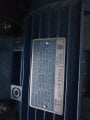
I have taken pictures of both plates, I hope they show the requited data.
My simple mind figured both motors were 240v 10A, with different outputs - the fact that the current draw might be nearly double is a learning moment for me.
There you have it, if my reading is correct. 11.7 amps should trip the overload protection after a bit.
A "motor with a slight increase in power. "I guess, is indeed slight if it is in a care with 320 HP. So it seems that "slight" is a relative term. Glad to have been able to help with the solution.
I'm reading 6.7A on the data plate of the new motor - is there something I'm missing in regards to the 11.7?
To fix this - do I have to go with a 15A power outlet? Or something else entirely?
(Yes, I said slight increase in power - its the way I talk, which unfortunately doesn't come across in writing very well. Something for me to remember.)
OK, the photo was not very clear on my screen. That seems about right for a 3/4 HP motor using 230 volts.
No matter what, there are 760 electrical watts per horsepower at 100% efficiency, and so that will help you to calculate the minimum possible current for a given voltage and HP.
new motor power: 760 W/HP x 1.5HP =1140 watts
And it seems that somehow my thinking shifted back to 120 volt power. I may have been a bit distracted at the time
It wasn't a very good photo I'm afraid, on anyone's screen. Just due to how difficult it is to get a picture that picks up the stamped data, and the printed data at the same time. Some compromise was made.
I am really appreciative of the help thus far, thank you all very much.
I'm talking with the motor supplier at the moment to see if they have any ideas.
Really, for this part all I need is the voltage and the amps. If the HP is twice the other motor then the current is probably about twice as much and that will trip a correctly sized overload that was sized for the original motor, even though there is nothing wrong with it.
The motors are connected through that sandwich switch, directly to the wall outlet/power board, not through anything rated specifically for the old motor vs new motor.
Essentially take the lathe/old motor out of the equation.
With this in mind, I would imagine as long as the motor can run fine with the available wall power (should be able?) and my wiring isn't short circuited somewhere, there should be no problems running it.
Really all I want to do is make sure that my wiring diagram was correct (at least on the right track). It seems to be, so the issue must be either inside the motor, or a short somewhere in the wiring.
As a thought, perhaps there's something wrong with the run capacitor. The breaker trips about 5 seconds after starting, I believe you can hear a slight 'click' as the (maybe centrifugal?) switch goes from start to run, then shortly after it stops. Would there be any issue in swapping the capacitors over to check?
With a light or no load on the motor I would expect the motor would be up to speed (And the contacts on the centrifugal switch open.) in less than a second. Try connecting your meter (Set to AC volts.) between V1 and V2. Watch the meter when you switch on the power to the motor. It should briefly read zero but when the centrifugal switch opens the reading should go up. I cant say exactly what this reading should be. Have you actually measured the motor current (And what was the reading.) ?
Certainly reading across the starting switch is a very good idea! But make sure thevoltmeter is able to handle the spike whan the switch opens. And it will be a bit of a spike, at least for most motors.
I feel I owe you folks an update as thanks for the help you've all provided - the very least I can do.
The issue turned out to be the switch, this was the original switch from day dot of this machine. And some of the contacts had corroded therefore were not closing properly. A clean up with a wire brush helped, but there was still an issue after a minute of running (gut feeling, there was arcing inside the switch which heated up some parts). So I have taken out the switch completely and will install another 2 switches in its place - one to switch directions and one to turn the motor on.
I didn't actually get around to measuring the motor current when running, I found it too hard to connect the terminals while switching on, at the same time as looking at the screen
Many thanks everyone for your input.
 Facebook
 Google
 GitHub
 Linkedin