 Facebook
 Google
 GitHub
 Linkedin
Hi,
I purchased a couple of the ubiquitous "electric arc lighter" devices off of Amazon because I was curious how the designers were able to pack a 3.7v to many kV step-up circuit in a package the size of a ballpoint pen.
I tested out the device and indeed it is able to make a ~4 mm sustained arc.
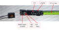
After opening up the device for inspection I found that the parts count is low and the circuit seemingly simple. Many of the components appear to be for the USB charging circuit.
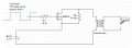
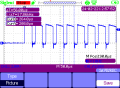
An unlabeled 8 pin chip appears to be the MCU. I measured a square wave coming off of pin 8 at ~17 kHz with a duty cycle of ~72%. This goes through a 10 ohm resistor to pin 1 of what almost certainly is a MOSFET (marked BN5T10AG 23335G). Pin 2 of the MOSFET goes to the (- marked) terminal of the transformer. A 10k ohm resistor connects MOSFET pin 2 to MOSFET pin 3 and battery ground. Battery positive passes through to the (+ marked) terminal of the transformer.
This appears to be a simple flyback circuit.
Next, I wanted to see if I could make my own driver circuit and bypass the marked-but-still-unknown-quality components. I decided to mimic the circuit as close as possible. I setup an STM32 to produce a square wave at the same frequency and duty cycle as the mystery MCU. I used a IRF832 for my MOSFET and included the 10 ohm and 10k ohm resistors in the same configuration as the original circuit. I powered the circuit with the same 3.7 li-ion battery.
My homemade driver does not cause any arc on the transformer output. I have been through the wiring and checked the signals on the scope but I am not sure what is going on. Any ideas on what I might be missing?
I purchased a couple of the ubiquitous "electric arc lighter" devices off of Amazon because I was curious how the designers were able to pack a 3.7v to many kV step-up circuit in a package the size of a ballpoint pen.
I tested out the device and indeed it is able to make a ~4 mm sustained arc.
After opening up the device for inspection I found that the parts count is low and the circuit seemingly simple. Many of the components appear to be for the USB charging circuit.
An unlabeled 8 pin chip appears to be the MCU. I measured a square wave coming off of pin 8 at ~17 kHz with a duty cycle of ~72%. This goes through a 10 ohm resistor to pin 1 of what almost certainly is a MOSFET (marked BN5T10AG 23335G). Pin 2 of the MOSFET goes to the (- marked) terminal of the transformer. A 10k ohm resistor connects MOSFET pin 2 to MOSFET pin 3 and battery ground. Battery positive passes through to the (+ marked) terminal of the transformer.
This appears to be a simple flyback circuit.
Next, I wanted to see if I could make my own driver circuit and bypass the marked-but-still-unknown-quality components. I decided to mimic the circuit as close as possible. I setup an STM32 to produce a square wave at the same frequency and duty cycle as the mystery MCU. I used a IRF832 for my MOSFET and included the 10 ohm and 10k ohm resistors in the same configuration as the original circuit. I powered the circuit with the same 3.7 li-ion battery.
My homemade driver does not cause any arc on the transformer output. I have been through the wiring and checked the signals on the scope but I am not sure what is going on. Any ideas on what I might be missing?
Attachments
-
 48.8 KB Views: 135
 -
 443.1 KB Views: 131
 -
 3.1 KB Views: 89


