Facebook
 Google
 GitHub
 Linkedin
I'm not sure if this is the correct place on this forum to be posting, so I apologize in advance. I don't want to get too bogged down in the details right away but let me present the problem and maybe from there I can dive deeper into the specifics.
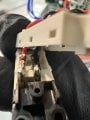
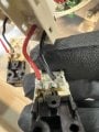
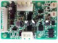
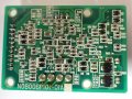
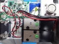
Let's say you have a PCB and no available schematic. The board is responsible for distributing voltages to various solenoids that control the movement of a valve. There is an analog voltage output that is proportional to a linear position of the valve. The board contains 5 trimmer pots, 2 of which are known to adjust the Zero and Span of the voltage reading.
The main question is, is there a way to understand the function of the other trimmer pots without messing up too much of the signal conditioning that's happening on the board? I don't imagine if someone made an adjustment to one and observed the effect and found it undesirable, they could simply set the pot back to the original value before an adjustment and expect the functionality to be restored?
If it helps anymore, the primary goal here is to essentially tune the output reading of this voltage for a controller to control the valve position.
")