hi,
You have to determine which peripherals are also using PORTC.
If you just do a TRISC, you may lock out a peripheral thats been defined in PORTC.
So which peripherals are using PORTC.??
E
hi,
You have to determine which peripherals are also using PORTC.
If you just do a TRISC, you may lock out a peripheral thats been defined in PORTC.
So which peripherals are using PORTC.??
E
Hi E,
Is this a question? [ If you are able to do a Bit Write to the Unused pins on PORTC.? ] I don't understand.
If you look at the images in #545 it shows that, TOP the ouput from the AK8963C when the PIC MISO is disconnected, then the output voltage is 3.3V, once the PIC MISO is connected, it attenuates the voltage down to 1.65V. BOTTOM of image.
C.
hi,
I assume the 18F is acting as the Master in the SPI interconnect to AK8... ?
As MISO is an Input to the 18F ie: Master In Slave Out, how can the 18F be pulling the MISO pin down to 1.8V
The AK must be setting the MISO pin to 1.8V.
Test: disconnect the MISO input to the 18F,,,, add a 1k pull down from the AK out pin to 0V, what voltage do you measure on the AK output pin.??
BTW: when I said Bit writes , I thought you were trying to use those used PORTC pins
I added a buffer into the AK8963C output, as the AK8 kept 'popping'. This inputs 3.3V and outputs 3.3V.
[ Test: disconnect the MISO input to the 18F,,,, add a 1k pull down from the AK out pin to 0V, what voltage do you measure on the AK output pin.?? ] Result 3.3V with 1K resistor to GND.
C.
hi,
I would say that there are three possible causes.
1. the pin has been set as an Output and Low State in the program.
2. if set as an Input, the pin is 'blown' internally.
3. There is PCB track problem
hi,
I would say that there are three possible causes.
1. the pin has been set as an Output and Low State in the program.
2. if set as an Input, the pin is 'blown' internally.
3. There is PCB track problem
Hi E,
1/ The pin is set to input.
3/ I've checked the PCB tracks, ok.
2/ The PIC must have blown, internally.
I have been concentrating on this PIN for so long, that I had forgotten, that I have a second PCB (SLAVE) I tried that and as you suggest all's well and the MISO is 3.3V connected to the PIC.
I'll change the PIC.
Thanks, C.
hi,
I would say that there are three possible causes.
1. the pin has been set as an Output and Low State in the program.
2. if set as an Input, the pin is 'blown' internally.
3. There is PCB track problem
Hi E,
1/ The pin is set to input.
3/ I've checked the PCB tracks, ok.
2/ The PIC must have blown, internally.
I have been concentrating on this PIN for so long, that I had forgotten, that I have a second PCB (SLAVE) I tried that and as you suggest all's well and the MISO is 3.3V connected to the PIC.
I'll change the PIC.
EDIT: Is there a way of protecting the PIN from this type of damage?
Thanks, C.
Hi, CORRECTION
On the working PCB the disconnected PIC MISO resistance to GND is app 15MOhm, on the none working PCB the resistance is app 12Mohm. The resistance between the MISO and the PIN is '0'
I checked the MISO PIN on the removed PIC against new ones, and it reads the same.
C
Hi,
The peripheral wires are longer on the none working PCB, is there a possibility that they are causing inductance or capacitance, that's effecting the MISO?
C
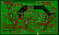
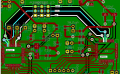
Hi E,
(I don't follow.? resistance between the MISO and the PIN is '0' ) From end to end the MISO wire is ok.
The interlink wire lengths are temporarily app 20CM.
Here is an image of the PCB: I was previously trying to use the second PIC 18F4431 as SLAVE, so the 18LF4620 MISO connects to the 18F4431 SDO (MOSI) Could this cause a porblem. I now use HSEROUT, so I could remove/cut the tracks.
C.
 Facebook
 Google
 GitHub
 Linkedin