Morning C,
Which programs are you referring too.?
I thought we were going to focus on just getting the HW SPI test running on the 4620 and 4431.??
Then you post it, so that I can upgrade the data being transferred.
E
Morning C,
Which programs are you referring too.?
I thought we were going to focus on just getting the HW SPI test running on the 4620 and 4431.??
Then you post it, so that I can upgrade the data being transferred.
E
Next to integrate my MAIN programs that work with the peripherals. The results of the 18F4620, shown on this thread at #428. And the 18F4431 I had previously got working with the INCREMENTAL ENCODER.
While integrating, I got mixed up and have to right back to all of the originals and try again. (Lets hope I get it right this time) EDIT:
C.
Hi E,
Here are the 2x programs, plus an analysis.
Unfortunately they have stopped talking to each other.
Note; I started again, so I must have made a mistake
C.
Hi E,
I found the latest programs, but if you recall [ CR ] wasn't accepted by Oshonsoft, so I changed it to [ CRTN ] now this isn't accepted, so I've changed it to [ CARTN ] which is accepted.
I'm sure these programs worked at one time, but today they don't.
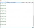
I've attached the Analysis, the C.S.V. and the terminal output.
EDIT: A previous post regarded the importance of the SLAVE running faster than the MASTER. I can add a XTL, then switch on 4xPLL if this is a good idea.
hi,
The csv file shows SPI data OK.????
Are you using a xtal on the 4620, you have HS set in the CONFIG header, if yes, waht is the xtal frequency.
Otherwise the two progs are identical with the ones I posted, with exception of the pin assignment.
E
hi,
The csv file shows SPI data OK.????
Are you using a xtal on the 4620, you have HS set in the CONFIG header, if yes, waht is the xtal frequency.
Otherwise the two progs are identical with the ones I posted, with exception of the pin assignment.
E
hi,
If they are both running at 8Mhz, as I had during the test, thats OK.
Have you made any hardware changes since you successfully ran those two programs.?
Any reason why you are not using the 4620 internal 8MHz oscillator.?
E
BTW: as you are using the latest Oshonsoft IDE's, why are you using Crlf Dim's in the Slave .?
hi,
Looking thru that csv file, the MSO and MSI seem to exchanging data ok.
If you were running my test programs, where are all the other alphanumeric characters coming from, on that csv list.??
E
hi,
If they are both running at 8Mhz, as I had during the test, thats OK.
Have you made any hardware changes since you successfully ran those two programs.?
Any reason why you are not using the 4620 internal 8MHz oscillator.?
E
BTW: as you are using the latest Oshonsoft IDE's, why are you using Crlf Dim's in the Slave .?
hi,
These Dims are not required
'Cartn = Chr(0x0d) ' redundant
'lfd = Chr(0x0a)
The Cr and Lf codes are now a part of the latest Oshonsoft compiler.
ie:
Cr ; Carriage Return
Lf ; Line Feed.
In your actual BMP program you do not require any Cr or Lf Codes, they are were only for testing using ASCII bytes,, ie: ERIC 1234 etc...
If you do include them, remember you are Writing/Reading Binary Data Bytes, which could include 0x0D and 0x0A as part of the Data group, so do not use these line terminator Codes.
Hi,
Previously when converting the SWSPI to HWSPI, we used a DUMMY in each READ/WRITE, is this still relevant or is this the same as the DATA SWAP?
------------------------------------------------------------------------------------
altmtr = 0
SSPBUF = 0xf4
While Not SSPSTAT.BF
Wend
dta = SSPBUF
WaitMs 5 '2
SSPBUF = dummy
While Not SSPSTAT.BF
Wend
dta = SSPBUF
WaitUs 5 '2
Hserout "F4 ", #dta, CrLf
altmtr = 1
-------------------------------------------------------------------------------
C
refers to the SLAVE clock speed should be faster than the MASTER.
At the moment both are at 8MHz, but if the SLAVE is slightly slower than the MASTER, would this be a problem. If so I can add a XTL to the SLAVE which is faster.
C.
hi C,
You are mixing the descriptions up, are you asking about Master <> Slave or Master to BMP
I have already covered this point, run them both at 8MHz using the internal clocks.
You had the test programs working this way, so why do you keep changing the set up.?
The code fragment in #455 is wrong, why is there a 5 milli-sec delay.?
altmtr = 0
SSPBUF = 0xf4
While Not SSPSTAT.BF ' this sends the Reg Addr 0xF4 to the BMP
Wend
dta = SSPBUF ' this is invalid data from the BMP, due to the 0xF4 Write, its not wanted in the 'dta' 'WaitMs 5 '2
SSPBUF = dummy
While Not SSPSTAT.BF
Wend
dta = SSPBUF ' you are now overwriting the invalid data in the 'dta' with the requested Reg data
WaitUs 5 '2
Hserout "F4 ", #dta, CrLf
altmtr = 1
Hi,
I was referring to 2xPICs as MASTER and SLAVE. Previously, I've been naming e,g, BMP280 as MODULES, but changed to PERIPHERALS. All of the PERIPHERALS are working OK, only the 2x PIC MASTER and SLAVE weren't talking to each, now they are.
Many of your questions, refer to tests I try to find faults, when the two PICs aren't talking to each other. This is nothing to do with BMP280, that's been working ok.
True, I had both PICs running at 8MHz, but only when I added an 8 MHz XTL to the 18F4620.
As there was a fault, I questioned slight variations on the INT OSC of the 18F4431, so tried OSCTUNE at full speed, which you may guess did nothing.
As this PCB is getting tired I re-checked for whiskers and failed solder. Some where there was a problem, as it's now working.
Soon, once the rest of the PERIPHERALS, including the SLAVE working, I'll have some professional PCBs made up.
hi,
This is one of the reasons why I prefer to debug designs on bread board [ when possible] , it saves lots of time and reworking.
I guess you know that you can get adaptor PCB's for most surface mount devices.
Ref the timing, try to keep the response time of the peripheral device as fast as possible, one way is to write linear code rather than Calls to subroutines.
When this project started, I used breadboards, and through the hole PICs, but since upgrading, some of the PERIPHERALS need the later chips e,g, (AK8963), so I needed to use surface mount, and moved over to SM PICs also. It has caused problems, but I used to get problems before. Remember this is now quite a complicated PCB, to wire on a breadboard
 Facebook
 Google
 GitHub
 Linkedin
") )
)