Remote control by location (PIC in Oshonsoft)

Thread Starter

camerart

Joined Feb 25, 2013
3,730
hi C,
You cannot sync the Base and Remote serial input sources, they are running asynchronously.

The DataSw you have, will select the desired Base or Remote into the UART, but the unselected serial source will not stop sending data, so when you switch the DataSw over, you may have missed part of that unselected message.[ say you are half way thru for example]
You need to read any partial serial message upto the LF code, keep that source selected and wait for the $ for the start of the message you have selected.
This applies to both messages Base and Remote.

E
Hi E,
There was a comment on another thread regarding the length of time the $sentences would take to 'go through', which is about 1/2 second (I think)
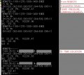
Here is the list of sentences, which I think are always sent in the same order.
They seem to be sent on the second, looking at some received sentences, and if, somehow using these clocks, checking of the GPS could be just before the [$GPRMC ] sentence, instead of this worst case scenario, as it is now the BASE could start checking here, marked in RED.
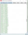
$#GPRMC,162254.00,A,3723.02837,N,12159.39853,W,0.820,188.36,110706,,,A*74
$GPVTG,188.36,T,,M,0.820,N,1.519,K,A*3F
$GPGGA,162254.00,3723.02837,N,12159.39853,W,1,03,2.36,525.6,M,-25.6,M,,*65
$GPGSA,A,2,25,01,22,,,,,,,,,,2.56,2.36,1.00*02
$GPGSV,4,1,14,25,15,175,30,14,80,041,,19,38,259,14,01,52,223,18*76
$GPGSV,4,2,14,18,16,079,,11,19,312,,14,80,041,,21,04,135,25*7D
$GPGSV,4,3,14,15,27,134,18,03,25,222,,22,51,057,16,09,07,036,*79
$GPGSV,4,4,14,07,01,181,,15,25,135,*76
$GPGLL,3723.02837,N,12159.39853,W,162254.00,A,A*7C
$GPZDA,162254.00,11,07,2006,00,00*63

so it would not get the next [ $GPRMC ] sentence for > a second.

C.
 

Thread Starter

camerart

Joined Feb 25, 2013
3,730
hi C,
You cannot sync the Base and Remote serial input sources, they are running asynchronously.

The DataSw you have, will select the desired Base or Remote into the UART, but the unselected serial source will not stop sending data, so when you switch the DataSw over, you may have missed part of that unselected message.[ say you are half way thru for example]
You need to read any partial serial message upto the LF code, keep that source selected and wait for the $ for the start of the message you have selected.
This applies to both messages Base and Remote.

E
Hi E,
I looked a bit closer into the Ublox GPS modules, and found a lot about timing. As it's quite involved, I'll start another thread, thanks.
C
 

Thread Starter

camerart

Joined Feb 25, 2013
3,730
Hi, TRANSMITTER.

Previously I connected the STICK pots and today I connected the INCREMENTAL ENCODER, which are working, so now all of the modules GPS,COMPASS etc are working.
A milestone has been reached after only a couple of years :)
C.
 

ericgibbs

Joined Jan 29, 2010
18,872
hi C,
Only a couple of years, it seems much longer...:rolleyes:

When are you going to post a few photo's or better still, a video showing the Project in action.

Eric
 

jjw

Joined Dec 24, 2013
823
Hi, TRANSMITTER.

Previously I connected the STICK pots and today I connected the INCREMENTAL ENCODER, which are working, so now all of the modules GPS,COMPASS etc are working.
A milestone has been reached after only a couple of years :)
C.
Do you mean they are working correctly or the modules compile?
 

Thread Starter

camerart

Joined Feb 25, 2013
3,730
Hi E and J, TRANSMITTER
J, I mean that the PCB uses modules, Compass, Altimeter, GPS, 5110 Screen, Joysick pots,and incremental encoder, which have taken a long time to get working.

Working means that they all INPUT to the program using 2x PICs 18F4620, and 18F4431 for the Encoder.

E,
This is an extension to the TRACKER PCBs and programs, that was started a perhaps 2015?

Next to do is a program section that is nearly working.

Then get all of the modules to perform at once, watch this space.

Once the TRANSMITTER is working on all cylinders, then on to the RECEIVER, which is very similar, so shouldn't be to much of a problem.

Then the control needs to be added to the programs, so that the TRANSMITTER tells the RECEIVER how to control the REMOTE.

I'll post some photos, but it will be the previously shown TRANSMITTER with the previous shown PCB, within it. EDIT: See #307

C.
 
Last edited:

Thread Starter

camerart

Joined Feb 25, 2013
3,730
Hi,
There are a couple of glitches in the program here's one.

See attached image:

Stepping through the program, it is stopped at the point where all the 'now' 5 X MSG1 are 'in' but the LOOP keeps going and as the next STRCHR is <> "," then the last MSG1 get's replaced by a ? or other digits.

How do I stop the LOOP after all the MSG1's are 'in' ?
C.
 

Attachments

Thread Starter

camerart

Joined Feb 25, 2013
3,730
Hi, TRANSMITTER
Update:

Here's SCREEN SHOT of the computer terminal showing the MAIN PIC 18F4620 is now collecting READings from connected modules and RECEIVING DATA via radio from the computer emulating REMOTE DATA.

There are still problems, e,g, see above #427
The DATASWITCH switch over needs better coordination, so the 2x DATA inputs are inputted cleaner, also there is an INCREMENTAL ENCODER READing on the 18F4431 to be READ via SPI.

So for the first time all of the modules are working, now to get it all working cleanly.
:)
C.
 

Attachments

Thread Starter

camerart

Joined Feb 25, 2013
3,730

Attachments

Last edited:

Thread Starter

camerart

Joined Feb 25, 2013
3,730
Hi,
Here is the MASTER program:
The 4620 program at #429 needs to be integrated into it.

This is quite a long program for me to check, but it's working with the Oshonsoft SW SPI settings as seen by the 'Results' image:
The Oshonsoft SPI needs removing and replacing by the HW SPI in the #429.

EDIT:
Here is the SLAVE program:
It READs the Incremental encoder, and the OUTPUT is shown on the IMAGE.
This needs to be made to match the MASTER program.
C.
 

Attachments

Last edited:

ericgibbs

Joined Jan 29, 2010
18,872
hi,
When the HW SPI version is ready, post it.
As you have changed the SPI Port from PORTC to PORTD means I cannot run a check on my rig, unless I change the program to suit a 18F2341.
Is there a reason why you changed from C to D.?
E
 

Thread Starter

camerart

Joined Feb 25, 2013
3,730
hi,
When the HW SPI version is ready, post it.
As you have changed the SPI Port from PORTC to PORTD means I cannot run a check on my rig, unless I change the program to suit a 18F2341.
Is there a reason why you changed from C to D.?
E
Hi E,
I've updated #432.
The reason I changed the SPI PORT from C to D is to match my PCB, see image:
C
 

Attachments

Thread Starter

camerart

Joined Feb 25, 2013
3,730
Hi E,
In my programs as in #432, the programs run from top to bottom. Set-up of PIC first then initialisation of peripherals, then LOOP. In your programs, as #429 you CALL the initialisation from after END.
Is there a reason? Why do you do it this way?
C.
 

ericgibbs

Joined Jan 29, 2010
18,872
hi C.
For about 30 years I programmed using assembler coding, so after a while I created blocks of proven code for various peripherals and internal MCU hardware.
I found it easier to copy/paste all the proven initialisation subroutines at the end of the main 'glue' coding.

Also used 'include' files for Dims, font tables etc.... at the top of the listing, again to shorten the program listing.

After all when you are writing 'new' code you want it to appear near to the top of the listing, avoiding scrolling up and down the displayed listing, looking for the section of code you are developing.

I wrote hundreds of programs over the years for all types of equipment, using an assembler I wrote myself.

In a commercial environment, time costs money, so any procedure that shortens the development time should be used.

So the simple answer to your question, I would say 'it works for me', other may have their own ideas.

E
 

Thread Starter

camerart

Joined Feb 25, 2013
3,730
hi C.
For about 30 years I programmed using assembler coding, so after a while I created blocks of proven code for various peripherals and internal MCU hardware.
I found it easier to copy/paste all the proven initialisation subroutines at the end of the main 'glue' coding.

Also used 'include' files for Dims, font tables etc.... at the top of the listing, again to shorten the program listing.

After all when you are writing 'new' code you want it to appear near to the top of the listing, avoiding scrolling up and down the displayed listing, looking for the section of code you are developing.

I wrote hundreds of programs over the years for all types of equipment, using an assembler I wrote myself.

In a commercial environment, time costs money, so any procedure that shortens the development time should be used.

So the simple answer to your question, I would say 'it works for me', other may have their own ideas.

E
Hi E,
OK. Thanks.
Can you imagine me working in a commercial environment? I'd be on screen/keyboard cleaning duties by now:). I have one include: For FONT

As my main program has taken years to write, and I'm kind of used to it's'shape', I'll carry on as it is now and see what happens. I can always try the E.G. method later.

At the beginning of your program, you have the TRISs. They are set-up like this:
'----------------------------------------------------------------------------------------------------------------------
TRISA = %00000001
TRISB = %00000000
TRISC = %00000001
PORTA = %00000001
PORTB = %00000000
PORTC = %00000000
PORTE = %00000000
'---------------------------------------------------------------------------------------------------------------------------
Are they set like this for a reason?
C
 
Last edited:

ericgibbs

Joined Jan 29, 2010
18,872
hi C,
That TRISx is a hangover from a program you posted, which I modified to suit my SPI version.
I know that you find your labelling and comments, 'shape' etc helpful in your understanding of the code, so I left it in, change it as you see fit.

I am looking forward to seeing the HW SPI of program #432

E

Correction.
 
Last edited:

Thread Starter

camerart

Joined Feb 25, 2013
3,730
hi C,
That TRISx is a hangover from a program you posted, which I modified to suit my SPI version.
I know that you find your labelling and comments, 'shape' etc helpful in your understanding of the code, so I left it in, change it as you see fit.

I am looking forward to seeing the HW SPI of program #432

E

Correction.
Hi E,
Ok, good.

Me too.
C
 

Thread Starter

camerart

Joined Feb 25, 2013
3,730
Hi,
It was looking promising, until I got mixed up!
I've had to go back to the original programs and start again:mad:

EDIT: just noticed I hadn't posted the Font file yet! Here it is:
I have the Font INCLUDE switched off, for now.
C.
 

Attachments

Top