No. When the Starter Relay is energized by the Ignition Switch, it energizes the solenoid switch in the Starter Motor.
The Ignition Switch is spring deactivated when you take your hand of the ignition key.
No. When the Starter Relay is energized by the Ignition Switch, it energizes the solenoid switch in the Starter Motor.
The Ignition Switch is spring deactivated when you take your hand of the ignition key.
But there is still the problem that everything else only gets power when the relay is engaged, which means that there is no way to engage the relay because the circuit that would engage it has no power.
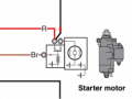
Look at the physical wiring of many old cars, especially ones like old Fords that had fender=mounted starter solenoids. The hot wire went directly to one post on the solenoid and that same post is where all of the other 12 V circuits branched off from.
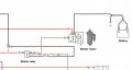
The 'R' wire in the diagram appears to be the 12 V hot side of the battery. If that's correct, then the positive side of the battery needs to connect directly to the 'R' wire. But, it almost certainly does NOT do so all the way down at the starter, even though electrically that would be fine.
This makes it more likely that the battery Hot cable is physically connected to the 12 V power bus at the starter relay (as accomplish by simply moving the wire from the battery to the left-hand post WITHOUT moving the 'R' wire from that same post).
This makes it more likely that the battery Hot cable is physically connected to the 12 V power bus at the starter relay (as accomplish by simply moving the wire from the battery to the left-hand post WITHOUT moving the 'R' wire from that same post).
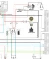
But unless we see the entire schematic, as least enough to see how that 'R' wire is used, we can't be sure.
Consider that several views showing portions of a circuit showed what was obviously incorrectin the portion that was shown, it seems that the case for checking even parts of drawings is clear.
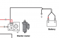
I ALSO noticed the error in post #1! But in post #7 it was corrected. Post #2 describes the correct functioning but does not seem to have noticed the error shown in the post #1 drawing.
Fortunately the drawing is corrected when next we see it.
It was a bit disturbing to see a description of how it actually works without any reference to the fact that the drawing had an error. A simple statement of "OOPS, that drawing is wrong" would greatly enhance one's credibility.
This makes it more likely that the battery Hot cable is physically connected to the 12 V power bus at the starter relay (as accomplish by simply moving the wire from the battery to the left-hand post WITHOUT moving the 'R' wire from that same post).
But unless we see the entire schematic, as least enough to see how that 'R' wire is used, we can't be sure.
But there is still the problem that everything else only gets power when the relay is engaged, which means that there is no way to engage the relay because the circuit that would engage it has no power.
it is clear that it is not drawn clearly.
it looks like who ever drew that meant to suggest that when energised, relay contacts are pulled down (towards coil) .
that way contact inside starter motor is NC (energised to open) and contact inside starter relay is a NO.
then while motor starter is energised, power to everything else would be cut... so what ever controls starter relay would need to have backup power (capacitor?).
it is clear that it is not drawn clearly.
it looks like who ever drew that meant to suggest that when energised, relay contacts are pulled down (towards coil) .
that way contact inside starter motor is NC (energised to open) and contact inside starter relay is a NO.
then while motor starter is energised, power to everything else would be cut... so what ever controls starter relay would need to have backup power (capacitor?).
You still have the situation that the battery is permanently connected to the starter motor so that it runs continuously.
But, leaving that aside, does it make any sense at all that someone designing an electrical system for a boat motor is going to design it so that there has to be a backup power supply of some kind to power everything else in the system, including the starter relay, while the engine is cranking. Just think of what's going to happen if the motor doesn't start quickly enough (using your suggestion of a capacitor). The capacitor runs down enough so that the starter relay drops out, this disengages the motor and reconnects the battery to the rest of the electrical system, which will charge the capacitor up just enough to re-engage the starter motor, taking a fraction of a second, which will then disconnect the battery and re-engage starter motor, but since it only charged up just barely enough to re-engage the starter relay, it will proceed to drop out again almost immediately, resulting in nothing more than a chattering of the relays, probably destroying them in short order.
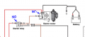
It seems people are having trouble understanding what is meant by the battery should be connected to the left-hand terminal of the starter solenoid. So here it is explicitly:
No, we can't, because we (or at least I) are making an assumption about that wire marked 'R', namely that it is intended to be directly connected to the battery without going through any other components, including a terminal block or fuse or anything else. This diagram is not only a schematic, but intended to show exactly which components the various wires physically connect to -- that's why they have pictures of each component so that the person using it can identify them visually when looking at the installation.

 Facebook
 Google
 GitHub
 Linkedin