Is -0.1v an ok reading post Reverse Polarity Protection Circuit?

Thread Starter

jtrier_itc

Joined Jun 12, 2026
11
Hey all,

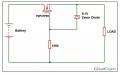
I grabbed a schematic online and created a Reverse Polarity Protection Circuit using a P-Mosfet, Zener Diode, and a resistor to pull at the Gate. It seems to work great, but when I reverse polarity I still get between -0.1v to -0.06v. Is that enough to cause damage to equipment? Or is that negligible?

Thank you!
 

Thread Starter

jtrier_itc

Joined Jun 12, 2026
11
Thanks ronsimpson. A 25watt touch screen monitor that can handle between 10v-36v.

Edit: This is being placed just after the 12v main battery supply.
 

Thread Starter

jtrier_itc

Joined Jun 12, 2026
11
Thanks crutschow. That's what I was thinking and was hoping for as a result. Even if there is a tolerance, I would really love to dial this in and do it right.

After researching a bit, I landed on the following components for a 12v battery:
  • FQP47P06 - 60V P-Channel QFET
  • OK1045E-R52 - 100K Ohm 1/4W 5% 250 Volt Resistor
  • 1N4742A - 1000mW, 5%, Zener Diode

Do you think it might be the diode?
 

Thread Starter

jtrier_itc

Joined Jun 12, 2026
11
Sorry about that! For some reason I read "post schematic" as "after the schematic". My bad. :)

Here is the diagram I used, but opted for a 12v Zener. Reverse Polarity Protection General Schematic.png
 

drjohsmith

Joined Dec 13, 2021
1,630
The simple way of providing reverse voltage protection, is just a diode.
either in series with the power rail, disadvantage with high current due to voltage drop across the diode
or
if you want hard protection, put a fuse in the posotive line, and a diode across the power rails, such that high current will flow through diod if have reverse current and pop the fuse
 

crutschow

Joined Mar 14, 2008
38,683
Here is the diagram I used, but opted for a 12v Zener.
That circuit should have a reverse current of <1µA.
What was the load when you measured the -0.1V?
Was it just a multimeter?

Note that for a 12V battery source, you don't need the Zener or the resistor, as that MOSFET can tolerate a Vgs of 25V.
Just connect the MOSFET gate directly to ground.
The simple way of providing reverse voltage protection, is just a diode.
Of course, But the TS's circuit is a common (and relatively simple way) to block reverse voltage without the forward drops of a diode.
The drop is just the load current times the MOSFET's on-resistance.
 

Thread Starter

jtrier_itc

Joined Jun 12, 2026
11
Thanks drjohsmith, I appreciate that. I considered those options but landed on using a P-mosfet to limit voltage drop and heat. It seems consensus is that it's a better way to go, but more expensive. Also, I like challenging myself as long as I don't cause damage. ;)

I have an inline fuse ready to be inserted between the battery positive and the RPP circuit once I am happy with the voltage tests on the meter. Thanks again!
 

Rf300

Joined Apr 18, 2025
112
Thank you for posting the schematic. The -0.1 V you can see at your load is caused by the reverse leakage current of the FET times the load resistance. Therefore you don't need to worry about damaging your circuit. As long as the reverse voltage is lower than the breakdown voltage of the FET the current will be limited to the reverse current of the body diode of the FET.

It is the current that damages a device, not the voltage.
 

Thread Starter

jtrier_itc

Joined Jun 12, 2026
11
Then that explains the measured voltage since the MOSFET leakage current flows through the typical multimeter 10MΩ input resistance.
Any practical load should have an impedance much less than that.
Thanks crutschow. This prompted me to look up "how to determine mosfet leakage", and it looks like I have some more chart reading and bench testing to do when using these. I appreciate it.
 
Top