Reading a schematic

Thread Starter

ulms

Joined Mar 19, 2024
194
You COULD go with a DPDT switch. That way you're only using one battery at a time. You just need to be creative when charging the second battery. I'll see what I can come up with and post it in a minute or two. Or 20.
Ill work with this switch. They're popular, readily available and can handle the amperage.

And getting back to the error in the "official" service manual for factory trained techs. Having an engine failure in a 7 knot current narrow channel hurling you out into the ocean lined with rock jettys is no place for a silly straw etch a sketch spirograph schematic!
 

B-JoJo-S

Joined Jan 3, 2026
533
OK, two options:
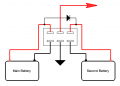
First is with a DPDT switch.
Screenshot 2026-09-21 at 7.16.50 AM.png
The red arrow indicates connection to the boat electricals, instruments, alternator, etc.
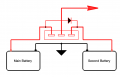
The second is the same thing but only using a SPDT switch.
Screenshot 2026-09-21 at 7.17.02 AM.png
Couple of notes here: The diode bridging the two batteries should be robust enough to handle whatever current the second battery may draw during charging. The second is the switch: It must be robust enough to handle ALL the electricals, including starting the motor.
 
Last edited:

B-JoJo-S

Joined Jan 3, 2026
533

panic mode

Joined Oct 10, 2011
5,244
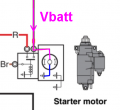
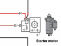
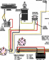
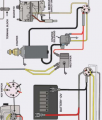
nothing in this small clip looks wrong, just missing bits .
having Vbatt connected permanently and directly to motor is wrong.
also having that built in relay that is meant to start the motor but actually has no effect on motor is also wrong.
relay representation is also wrong. contact is shown as push button, and gap between contacts suggests contact is NO type.
so activating that relay would apply power to something else, not the starter motor...

to be sure one would need to remove wires from two posts on top and check continuity, from each post to GND, as well as from one to another when coil is energized and deenergized (Br wire)

1789998218297.png
 
Last edited:

panic mode

Joined Oct 10, 2011
5,244
that was the long debate - about what part of this drawing is actually wrong. is it wiring... or depiction of inner working of the components.

it is more likely that wiring as shown is correct or things would go horribly wrong very soon. depiction of inner working is likely meant just for orientation and never scrutinized (i hope that is the case...).

perhaps it was meant to be something like this (just one guess):
1789999326101.png

starter relay is regular relay, probably rated no more than 30A. way too low to handle starter current. but that is more than enough to energize solenoid inside starter motor, which then handles high starting current (200-400A)
 
Last edited:

panic mode

Joined Oct 10, 2011
5,244
how do you know? the only YT references seem to be your posts. TS says this is from service manual he purchased from Yamaha. was it misread? or you have additional info?
 

WBahn

Joined Mar 31, 2012
33,186
Said it before, will say it again, the drawing is poorly done. Yes, it may very well be done by some intern or graphics artist who has no understanding of the electrical workings of the components depicted. Most - if not all - of us can pick the drawing apart for its numerous errors and vaguerry. (made-up word there). Someone with your knowledge and experience can decipher the drawing with no problem. But not all of us have your level of skills and experiences. Even having the whole drawing - it still looks to be incorrect.
And I said it before -- at least three times -- YES, the diagram appears to be incorrect! I have NEVER said that is was correct. Not Once!

I have said REPEATEDLY, that the most like case is that the wire from the battery is supposed to go to the OTHER terminal.

Though it is possible that the internal wiring of the solenoid is like that shown by @panic mode, I rather doubt it.

If the TS could give use more specific information about exactly what motor this is, instead just it being some Yamaha motor in a boat, we might be able to track down better information.
 

WBahn

Joined Mar 31, 2012
33,186
It's a YouTube drawing. Might as well ask AI for help. YT is like a box of chocolates. You never know what you're going to get.
Why do you keep claiming that the drawing if from YoutTube? The TS has stated several times that it is from the Yamaha Service Manual that he purchased from Yamaha.
 

MrChips

Joined Oct 2, 2009
35,171
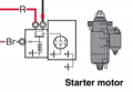
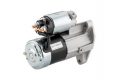
Every starter motor I have removed and replaced had two terminals on the starter solenoid.
One terminal is connected to the motor via a heavy gauge braided copper wire. No other wire is connected to this terminal. The battery cable is connected to the second terminal.

1790003630606.png

This is the corrected wiring:

1790003784941.png
 

Thread Starter

ulms

Joined Mar 19, 2024
194
that was the long debate - about what part of this drawing is actually wrong. is it wiring... or depiction of inner working of the components.

it is more likely that wiring as shown is correct or things would go horribly wrong very soon. depiction of inner working is likely meant just for orientation and never scrutinized (i hope that is the case...).

perhaps it was meant to be something like this (just one guess):
View attachment 371566

starter relay is regular relay, probably rated no more than 30A. way too low to handle starter current. but that is more than enough to energize solenoid inside starter motor, which then handles high starting current (200-400A)
The boat is in the water right now, so I can't get a look at that.But trust me , when I get it home at the end of the season , i'm gonna look at that starter relay
 

Thread Starter

ulms

Joined Mar 19, 2024
194
And I said it before -- at least three times -- YES, the diagram appears to be incorrect! I have NEVER said that is was correct. Not Once!

I have said REPEATEDLY, that the most like case is that the wire from the battery is supposed to go to the OTHER terminal.

Though it is possible that the internal wiring of the solenoid is like that shown by @panic mode, I rather doubt it.

If the TS could give use more specific information about exactly what motor this is, instead just it being some Yamaha motor in a boat, we might be able to track down better information.
2017 F70 Yamaha outboard
 

MisterBill2

Joined Jan 23, 2018
28,253
My cars and van do not include that separate HIGH CURRENT "starter relay", instead that function is a part of the solenoid that engages the starter gear with the large gear on the flywheel.
Certainly the first few drawings had at least one error. I doubt very much that many vehicles have a second high current relay as shown having that same form factor but NC, to disconnect the rest of the vehicle circuits.
 

B-JoJo-S

Joined Jan 3, 2026
533
Its from a Yamaha boat motor factory service manual
I may be confusing another thread with this one. I could swear I saw the TS state that the drawing was from a YT video.
how do you know? the only YT references seem to be your posts.
"(
And I said it before -- at least three times -- YES, the diagram appears to be incorrect!
It's well established that the drawing is incorrect. We all know that. Some of us have even modified either the schematic or parts of the schematic the TS has posted.

I've looked and can't find any reference to YT, so I must be mistaken.

I hope my input has been helpful to the TS in that as I understand it - he wants to put two batteries on his boat, one as the main battery and the second as a backup.
 

WBahn

Joined Mar 31, 2012
33,186
2017 F70 Yamaha outboard
I did some looking online and finding a decent picture showing the electrical connections hasn't been easy, but I did find this one:

1790026360759.png
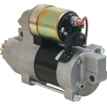
As you can see looking at the two high-current terminals of the solenoid, one of them is effectively inaccessible and connected directly to the motor under what looks like a pretty rigid shroud.

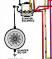
I also found several wiring diagrams for F40 to F70 motors and they all show the same thing, namely the hot wire coming into one side of the solenoid (sometimes showing that as the junction point for the hot branches) and the other side going only to the starter motor.

1790027260900.png
1790027330590.png
1790027435833.png

In looking for this I also ran across places that sell the starters. Sheesh! Nearly $400!!!!
 

WBahn

Joined Mar 31, 2012
33,186
My cars and van do not include that separate HIGH CURRENT "starter relay", instead that function is a part of the solenoid that engages the starter gear with the large gear on the flywheel.
Certainly the first few drawings had at least one error. I doubt very much that many vehicles have a second high current relay as shown having that same form factor but NC, to disconnect the rest of the vehicle circuits.
There aren't two high-current starter relays. There's a starter relay and there's a starter solenoid. Only the solenoid is high current. The relay is low current as it only has to provide current to the solenoid coil.

Most older cars powered the solenoid directly from the ignition switch. The solenoid itself was usually either mounted on the fender or something similar near the battery or was mounted on the start itself (like the Yamaha starter). I think the switch to using a relay to power the solenoid coil was driven by wanting to have a lot more say over when the starter could be activated and when it couldn't. Originally, you could activate the starter any time you could physically turn the key, which on my first few cars meant just about any time, including when the car was sitting in there in Drive or Reverse or even when going down the road. It relayed on drivers being smart enough not to do dumb things. But someone decided it would be better for the ignition switch to tell the computer that the key had been turned to 'Start' and then let the computer decide if all of the conditions were satisfied to actually engage the starter.
 
Top