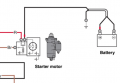
I just thought it was sad that I paid $80 for this factory manual from Yamaha and it's flakey at best. I could not find any schematics online and they are very big with the word proprietary. I had to buy it from the factory.
I mean like who am I to question these high and mighty engineers. Well , not so much the engineers as it is the giant corporation. Thanks to all for the input.
Manuals have errors. So do textbooks and datasheets and just about everything else.
There may be some kind of an errata sheet somewhere, but maybe not.
It's probably a case of the person preparing the artwork (who was, at best, a graphic artist, but more likely some intern) simply not catching that the two wires went to the same terminal of the part in question instead of one wire going to each of the two terminals. Fairly easy mistake to make. You would hope that the review process would have caught it, but they are reviewing the entire manual and it is easy to miss things because the reviewers may not be conversant with that particular system and likely aren't referring to the source schematic while they are reviewing it and they have a very limited time and many other things their plate. It's in imperfect world.
So did I, at first. I made the same assumption you did and that the question was based on not understanding how starter relays worked and that the fact that the power went directly to the component labeled as the starter was what was confusing. Fortunately, when I first came acress the thread, the TS's response to your response had already been posted and so I took a closer look.
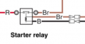
The drawing is not clearly drawn. The starter relay should be open at all times except when starting the engine. The drawing is of poor quality. The relay that controls the starter motor is also poorly drawn as it almost looks like it's normally closed, which would be incorrect. It should be normally open. The only time it closes is when you turn the key to start the engine.
As for the rest of the wiring, I didn't learn anything new from seeing the whole thing. In fact, it only lead to some confusion for me. But I'm easily confused these days.
The drawing is not clearly drawn. The starter relay should be open at all times except when starting the engine. The drawing is of poor quality. The relay that controls the starter motor is also poorly drawn as it almost looks like it's normally closed, which would be incorrect. It should be normally open. The only time it closes is when you turn the key to start the engine.
As for the rest of the wiring, I didn't learn anything new from seeing the whole thing. In fact, it only lead to some confusion for me. But I'm easily confused these days.
Keep in mind what these diagrams are intended for. They are primarily for use by someone that is wiring the system up and it really only needs to tell them which connections on which components which wire connects to. Would it be great if they were correct in every little detail of the internal representation of a component? Sure. But the real question is whether it is good enough for someone doing maintenance on the system to correctly rewire the system after replacing a component or a wire. As long as they can distinguish between which wires go to the coil of a relay and which wires go to the contacts of it, it serves its purpose.
it is far more likely that external connections (wiring seen or touched by user/owners) are depicted correctly and that mistakes likely belong to internal depictions (inside components).
external wiring mistakes would be something that should lead to problems that cannot be ignored. misinterpretation of internal working (like starter motor connection to one of the posts) may be something not many care about.
i do not disagree. in fact everyone agrees that drawing is not clear and that there must be mistake(s).
it is far more likely that external connections (wiring seen or touched by user/owners) are depicted correctly and that mistakes likely belong to internal depictions (inside components).
external wiring mistakes would be something that should lead to problems that cannot be ignored. misinterpretation of internal working (like starter motor connection to one of the posts) may be something not many care about.
If that starter solenoid mounted on the starter actually has two contact posts accessible, it very much matters which they connect to. But, more likely, there is only one contact post accessible as the other is directly connected internally to the motor. At the very least, those two wires do not go to different contact posts on the solenoid.
it is far more likely that external connections (wiring seen or touched by user/owners) are depicted correctly and that mistakes likely belong to internal depictions (inside components).
Based on what the TS said, the above screen shot shows the positive being wired directly to the battery. Even though MOST of that wire is black it has red tags on either end of the wire, which DOES look like the starter motor would in fact be continuously running with or without input from the solenoid.
For ME, the Starter Relay (SR) looks like it's Normally Closed (NC). Which when there's power the contacts of the SR it would energize the Starter Solenoid.
Keep in mind what these diagrams are intended for. They are primarily for use by someone that is wiring the system up and it really only needs to tell them which connections on which components which wire connects to.
Very true. However, the TS is not someone that is wiring the system up - the TS is questioning why the diagram shows what seems to indicate the starter motor should be running all the time, key or no key.
Said it before, will say it again, the drawing is poorly done. Yes, it may very well be done by some intern or graphics artist who has no understanding of the electrical workings of the components depicted. Most - if not all - of us can pick the drawing apart for its numerous errors and vaguerry. (made-up word there). Someone with your knowledge and experience can decipher the drawing with no problem. But not all of us have your level of skills and experiences. Even having the whole drawing - it still looks to be incorrect.
To ulms I say this: You are right - the drawing shows the starter motor constantly running the moment the battery is connected. You said you got the drawing from a YouTube video. YT Video's are questionable as to their accuracy, and should not be trusted 100% without knowledge of circuitry or verifying that the information being given is 100% correct. In this case it's not. Don't use that drawing for anything more than scrap paper (if you printed it out). It's basically useless and misleading.
Based on what the TS said, the above screen shot shows the positive being wired directly to the battery. Even though MOST of that wire is black it has red tags on either end of the wire, which DOES look like the starter motor would in fact be continuously running with or without input from the solenoid. View attachment 371554
For ME, the Starter Relay (SR) looks like it's Normally Closed (NC). Which when there's power the contacts of the SR it would energize the Starter Solenoid.
Very true. However, the TS is not someone that is wiring the system up - the TS is questioning why the diagram shows what seems to indicate the starter motor should be running all the time, key or no key.
Said it before, will say it again, the drawing is poorly done. Yes, it may very well be done by some intern or graphics artist who has no understanding of the electrical workings of the components depicted. Most - if not all - of us can pick the drawing apart for its numerous errors and vaguerry. (made-up word there). Someone with your knowledge and experience can decipher the drawing with no problem. But not all of us have your level of skills and experiences. Even having the whole drawing - it still looks to be incorrect.
To ulms I say this: You are right - the drawing shows the starter motor constantly running the moment the battery is connected. You said you got the drawing from a YouTube video. YT Video's are questionable as to their accuracy, and should not be trusted 100% without knowledge of circuitry or verifying that the information being given is 100% correct. In this case it's not. Don't use that drawing for anything more than scrap paper (if you printed it out). It's basically useless and misleading.
My friend I paid $80 to Yamaha. That is from the carefully guarded proprietary factory Yamaha service manual. What I want to do is install a 2 battery system. The boat is in the water, and it's difficult to study the connections so I thought I'd buy the manual so I could prepare for this install when the boat is out of the water this winter. I was interested in the charging connections.
Okay I want to get a batt 1/batt2/both switch and from what I learned on this site charging 2 parallel batteries is not a good idea. So I want to charge battery bank one. And if I am using battery bank 2 I want to charge that, but if I was using both batteries I was concerned about hurting the alternator.
Keep in mind what these diagrams are intended for. They are primarily for use by someone that is wiring the system up and it really only needs to tell them which connections on which components which wire connects to. Would it be great if they were correct in every little detail of the internal representation of a component? Sure. But the real question is whether it is good enough for someone doing maintenance on the system to correctly rewire the system after replacing a component or a wire. As long as they can distinguish between which wires go to the coil of a relay and which wires go to the contacts of it, it serves its purpose.
Okay I want to get a batt 1/batt2/both switch and from what I learned on this site charging 2 parallel batteries is not a good idea. So I want to charge battery bank one. And if I am using battery bank 2 I want to charge that, but if I was using both batteries I was concerned about hurting the alternator.
A Three Way Rotary Battery Switch can do what you're asking for. In Switch Position 1 (SP-1) the first (main) battery is in circuit while the second battery is disconnected. In SP-2 the second battery is in circuit and the first is disconnected. In SW-3 both batteries are connected in parallel, thus giving you more amperage or more amp hours of service time. Both batteries should NOT be charged at the same time because, as you said, you can hurt the alternator. One solution to that issue would be to install a heavy duty alternator if you can. You speak of a boat so I don't know if the motor is an outboard motor or if it's an inboard 455 Chevy engine, one which you Could change the alternator.
Back in 1993 I was gifted a Ford Country Squire Station Wagon which had a cracked frame. I scavenged several parts to add to MY Country Squire. The gifted one came with a higher output alternator but bolted right in and wired directly the way the OEM alternator was wired. I scavenged the starter solenoid (fender mounted) and put a high current bypass diode across the terminals so that a second battery (also scavenged) could be installed. Back then engine bays had a lot of spare room for stuff. The diode kept the second battery charged. When I needed the extra power from the secondary battery I just pushed a switch on the dash board that engaged the scavenged solenoid and added the second battery current to the starter. I was glad I did that one foggy morning. I forgot to shut the headlights off. When I came out of work the main battery was dead. Pushing the button added the second battery into the circuit. Held it for a few seconds before turning the key and starting the car without the need for a jump. The alternator was strong enough to handle charging the dead battery and restoring charge to the secondary battery. There WAS a voltage drop going to the second battery because of the high amperage diode. A few minor tenths of a volt that I did not think was going to be a problem. Instead of charging the battery to 13.8V it was charged closer to 13.0V. I don't recall what diode I used so I can't tell you what the forward voltage drop was. But it was always enough energy to get me out of trouble.
A Three Way Rotary Battery Switch can do what you're asking for. In Switch Position 1 (SP-1) the first (main) battery is in circuit while the second battery is disconnected. In SP-2 the second battery is in circuit and the first is disconnected. In SW-3 both batteries are connected in parallel, thus giving you more amperage or more amp hours of service time. Both batteries should NOT be charged at the same time because, as you said, you can hurt the alternator. One solution to that issue would be to install a heavy duty alternator if you can. You speak of a boat so I don't know if the motor is an outboard motor or if it's an inboard 455 Chevy engine, one which you Could change the alternator.
It's an outboard Im stuck with this alternator. I will just avoid charging both batteries at the same time. What I want to ultimately know is, if I was ever in this situation where I needed to use the both batteries to just run the starter motor would that hurt my alternator?
Potentially momentarily. It depends on how quickly you switch from 2 batteries back to one.
Realize this: If the primary battery should go dead but the second battery has had its voltage maintained similarly to how I did my station wagon, switching to the second battery should be sufficient to start the motor. Once started you could switch back to the primary battery and recharge it. In other words, you shouldn't need to use both batteries to start the motor.
Potentially momentarily. It depends on how quickly you switch from 2 batteries back to one.
Realize this: If the primary battery should go dead but the second battery has had its voltage maintained similarly to how I did my station wagon, switching to the second battery should be sufficient to start the motor. Once started you could switch back to the primary battery and recharge it. In other words, you shouldn't need to use both batteries to start the motor.
You COULD go with a DPDT switch. That way you're only using one battery at a time. You just need to be creative when charging the second battery. I'll see what I can come up with and post it in a minute or two. Or 16.

 Facebook
 Google
 GitHub
 Linkedin