Facebook
 Google
 GitHub
 Linkedin
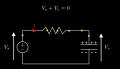
I am creating a video in Manim about basic electrical circuits. The circuit under consideration is an ideal RC circuit with a DC voltage source, no energy losses.
My reasoning is as follows:
My questions are:
1. Is this reasoning correct, or am I making a conceptual mistake in the way I apply Kirchhoff’s and Ohm’s laws?
2. Regarding the diagram: what is the correct direction of the voltage drop arrows across the resistor and capacitor? Are the directions shown in my image correct, or should they be drawn differently?
I would really appreciate clarification and references, since I want to avoid presenting misconceptions in the video.

My reasoning is as follows:
- When the current leaves the DC source and flows through the circuit, the capacitor starts charging. At some point, the capacitor voltage becomes equal to the source voltage.
- According to Kirchhoff’s Voltage Law, this means that the sum of the two voltages is zero:
- From Ohm’s law, this implies that the current I in the circuit becomes zero, so the current eventually stops flowing.
My questions are:
1. Is this reasoning correct, or am I making a conceptual mistake in the way I apply Kirchhoff’s and Ohm’s laws?
2. Regarding the diagram: what is the correct direction of the voltage drop arrows across the resistor and capacitor? Are the directions shown in my image correct, or should they be drawn differently?
I would really appreciate clarification and references, since I want to avoid presenting misconceptions in the video.