Is the delay circuit still powered solely by the input voltage or is there a separate power supply available?
Do you want a delay on both the high and low transition?
yes i have requested delay for both the transitions because it's like a safety check to ensure that supply is recieved and sensors are working fine an acknowledgement to the dashboard.
such that during that delay irrespective of whether Vin>Vref(HIGH) or Vin <Vref(LOW) there should be a high signal till that delay for acknowledgement purpose.After the delay based on the condition either low or high could be sensed by the comparator.
Thanks for the suggestion.actually already worked with microcontroller...
now trying to do without microcontroller only with comparator as a cost reductive product.
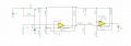
Here's the LM339/393 circuit modified with a TL431 reference configured as a series regulator to provide constant 5V power to the circuit.
The LTspice simulation shows the output going low at an ECO voltage of 2.68V and high at 2.33V with each transition delayed about 1 second, for both 12V and 24V power.
Is that what you wanted?
Yes crutschow almost i could get the functionality as per requirements...
but could you explain the functionality a little more clearly...
because i wanted to know the circuit more detailed....i have to make few modifications as well such that for simulations i will have to do like this test signal with reference, i real time i have to bring the voltage from two points for diesel n water as well na...
the reference of low n high is well done...
could you go with explanations clearly...
and the moment the sensor is getting supply what shall be the output till the delay...active low ??
Here's the LM339/393 circuit modified with a TL431 reference configured as a series regulator to provide constant 5V power to the circuit.
The LTspice simulation shows the output going low at an ECO voltage of 2.68V and high at 2.33V with each transition delayed about 1 second, for both 12V and 24V power.
Is that what you wanted?
I could moderately understand....but will be fine if you could come up with brief explanation
and another thing is the delay here is throughout the operation
I needed a startup delay alone....once switching on the sensor there should delay irrespective high or low sensing.
after that there shouldn't be any delay in output in giving after the comparator senses the high and low...
hope im clear...
startup delay crutcshow... i believe RC delay circuits serves the startup delay functionality...
I needed a startup delay alone....once switching on the sensor there should delay irrespective high or low sensing.
after that there shouldn't be any delay in output in giving after the comparator senses the high and low...
hope im clear...
Here ecu we can take it as 12/24v and another input signal to b compared is voltage of either diesel or water.
Here once the sensor is getting supply once vehicle is on(or 12/24v) a delay startup delay is needed
Here's the LM339/393 circuit modified with a TL431 reference configured as a series regulator to provide constant 5V power to the circuit.
The LTspice simulation shows the output going low at an ECO voltage of 2.68V and high at 2.33V with each transition delayed about 1 second, for both 12V and 24V power.
Is that what you wanted?
My last doubt is that if in case due to short circuit or any failure if the other input signal (say V_ECU) couldn't be obtained,what will be the output ?
So you want the delay only upon the application of power?
That will increase the circuit complexity.
A micro for this purpose, as danadak suggested, likely is the simpler and cheaper way to go.
I use LTspice because it's a good and free program.
The other Spice programs you mentioned likely have a wider range of built-in part models, so would be better from that point-of-view.
What i feel is that the 12/24V is to be obtained from the supply. so that will be obtained only when ignition is on in the vehicle, that 12/24v is the reference which is made as 5V clamped, other input to be compared is from pins inserted inside.
So i felt the delay whatever we give will be produced only at the ignition on(not for each and everytime there is change in other voltage to be compared)
I'm i right?
Here's the LM339/393 circuit modified with a TL431 reference configured as a series regulator to provide constant 5V power to the circuit.
The LTspice simulation shows the output going low at an ECO voltage of 2.68V and high at 2.33V with each transition delayed about 1 second, for both 12V and 24V power.
Is that what you wanted?
Here the components comparator and voltage regulator are missing in my library while trying to open.
any source to download them.
I NEEDED THESE MMBTT3904(TRANSISTOR), LM2901YDT(COMPARATOR) & TL431IDT(REGULATOR) LIBRARIES AS WELL....
CAN U HELP ME?
Here's the LM339/393 circuit modified with a TL431 reference configured as a series regulator to provide constant 5V power to the circuit.
The LTspice simulation shows the output going low at an ECO voltage of 2.68V and high at 2.33V with each transition delayed about 1 second, for both 12V and 24V power.
Is that what you wanted?
I'm facing few errors on output of the second comparator while trying with LM2901YDT comparator
changing only few things like low and high limits instead of (2.668 & 2.33) changed for (3.9 &4.2).
The second comparator remains high. But i tried it on Tina-TI
as the library of LT Spice isn't updated and my other software license approval is pending.
Can u help with it?
If u need i can even give the modified one for changing limits of voltage switching as well.
Here's the LM339/393 circuit modified with a TL431 reference configured as a series regulator to provide constant 5V power to the circuit.
The LTspice simulation shows the output going low at an ECO voltage of 2.68V and high at 2.33V with each transition delayed about 1 second, for both 12V and 24V power.
Is that what you wanted?
i have attached the screenshot below...can u check and say...what's wrong in circuit?
i tried for low at Vin>4.2 and Vin <3.9 high
 Facebook
 Google
 GitHub
 Linkedin