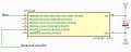
Here's a circuit using two small MOSFETs that shows very little change in delay (≈1%) for an ECU voltage between 12V to 24V.
The delay time can be varied by changing R1 and/or C1.
How would a circuit like that discharge the capacitor? A mosfet has a very high gate impedance. The next time it is powered up, how would there be a delay? So it might make sense to add a discharge resistor. Also, to avoid it being partially on, maybe use a BJT with a base zener, or a comparator.
Here's a circuit using two small MOSFETs that shows very little change in delay (≈1%) for an ECU voltage between 12V to 24V.
The delay time can be varied by changing R1 and/or C1.
Crutschow i have query of adding delay in functionality of a comparator used for presence of water in fuel(for eg diesel),
here two pins will be used for sensing their respective presence at different heights, based on that we the respective voltage has to be compared and respective output has be sensed.
But here a delay has to given in output. How could i introduce an delay in a comparator circuit in simple and effective manner.
any suggestions.
for your reference i would add an model reference Comparator circuit below
Another alternate delay circuit using only one IC, five resistors, and two capacitors, that has only about a 0.1% variation in delay time for the input voltage change.
R5 and C2 determine the delay time.
U1 provides a fast discharge of C2 when ECU goes to zero.
We can use a single quad comparator and use it as two comparators na??
can you explain the process overflow
where the signals needs to be compared will be acquired where the delay will be done?
Thanks for the suggestion.actually already worked with microcontroller...
now trying to do without microcontroller only with comparator as a cost reductive product.
Another alternate delay circuit using only one IC, five resistors, and two capacitors, that has only about a 0.1% variation in delay time for the input voltage change.
R5 and C2 determine the delay time.
U1 provides a fast discharge of C2 when ECU goes to zero.
As per my idea from the circuit,
R9 and R10 voltage dividers for reference voltage?
and R7 here is hysteresis purpose?
purpose of R6 is pull up resistance at output?
Is the delay circuit still powered solely by the input voltage or is there a separate power supply available?
Do you want a delay on both the high and low transition?
Is the delay circuit still powered solely by the input voltage or is there a separate power supply available?
Do you want a delay on both the high and low transition?
Yes i need for both high & low
high will be for some fuel and low will be for water
Supply from ECU(maybe 12-24V) input voltages which is to compared are from pins which will be seperate.
irrespective of sensing of high or low there should be a delay
To be precise, the delay has to be in the output(irrespective of whether high or low because here high or low is some presence of either water or fuel).
I'm i clear crutschow now?
 Facebook
 Google
 GitHub
 Linkedin