Facebook
 Google
 GitHub
 Linkedin
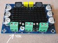
Gemini (AI) made this description, but could not complete the diagram (it still has some way to go). This is for a small, simple amplifier speaker "pop" protection delay curcuit (where using a 555 or UPC1237 is a bit overkill).
Maybe somebody (human) can help with in the details and complete it ?
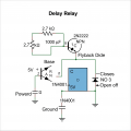
To make a delay relay that opens 3 seconds after power on (of the curcuit), but closes immediately on power off, you need to use an RC circuit combined with a transistor to control the relay. The key is to manage the capacitor's charging and discharging paths to achieve the desired timing.
Circuit Operation:
Power On: When power is applied, the capacitor begins to charge through a resistor. The transistor, which controls the relay, is initially off because the voltage at its base is too low. The relay's switch remains in its normally closed (NC) position.
Delay: As the capacitor charges, its voltage gradually increases. After approximately 3 seconds (depending on the resistor and capacitor values), the voltage across the capacitor becomes high enough to turn on the transistor.
Relay Activation (Opens Circuit): Once the transistor turns on, it allows current to flow through the relay. This causes the relay's mechanical switch to move from the normally closed (NC) position to the normally open (NO) position. Any load connected to the NC terminal is now disconnected, and the circuit "opens."
Power Off: When the power supply is removed, the voltage to the circuit immediately drops. A diode placed in parallel with the charging resistor provides a low-resistance path for the capacitor to discharge instantly. This rapid discharge causes the transistor to turn off immediately.
* Relay Deactivation (Closes Circuit): As soon as the transistor turns off, the current to the relay is cut. The relay's internal spring quickly pulls the switch back to its normally closed (NC) position. This immediately "closes" the circuit to the load connected to the NC terminal.
Key Components:
5V Relay: An SPDT (Single-Pole, Double-Throw) relay is best for this, as it has both a normally open (NO) and a normally closed (NC) terminal.
NPN Transistor (e.g., 2N2222): Acts as a switch to control the high current required by the relay coil.
Capacitor (e.g. 1000 µF): Stores energy for the timing delay.
Resistor (e.g. 2.7 kΩ): Limits the charging current to the capacitor and sets the delay time.
Diode (e.g. 1N4001): Two diodes are needed: one in parallel with the relay coil to protect the transistor from back-EMF, and a second one in parallel with the charging resistor. The second diode provides the immediate discharge path for the capacitor, ensuring the relay deactivates instantly when power is cut.
By adding a diode in parallel to the charging resistor, you ensure the capacitor bypasses the resistor and discharges very quickly, allowing the relay to return to its original state without a delay.
Gemini's attempt of drawing the curcuit was a bit lacking ...
P.S It doesn't even have to be a vey powerfull relay (or relay at all, maybe just the transistor) because I noticed that if the amplifier IN+ is grounded at power on, the "pop" is practically eliminated. Naturally it has stop being grounded after 3 seconds or there can be no input signal (and grounded again immediately at power off)
Maybe somebody (human) can help with in the details and complete it ?
To make a delay relay that opens 3 seconds after power on (of the curcuit), but closes immediately on power off, you need to use an RC circuit combined with a transistor to control the relay. The key is to manage the capacitor's charging and discharging paths to achieve the desired timing.
Circuit Operation:
Power On: When power is applied, the capacitor begins to charge through a resistor. The transistor, which controls the relay, is initially off because the voltage at its base is too low. The relay's switch remains in its normally closed (NC) position.
Delay: As the capacitor charges, its voltage gradually increases. After approximately 3 seconds (depending on the resistor and capacitor values), the voltage across the capacitor becomes high enough to turn on the transistor.
Relay Activation (Opens Circuit): Once the transistor turns on, it allows current to flow through the relay. This causes the relay's mechanical switch to move from the normally closed (NC) position to the normally open (NO) position. Any load connected to the NC terminal is now disconnected, and the circuit "opens."
Power Off: When the power supply is removed, the voltage to the circuit immediately drops. A diode placed in parallel with the charging resistor provides a low-resistance path for the capacitor to discharge instantly. This rapid discharge causes the transistor to turn off immediately.
* Relay Deactivation (Closes Circuit): As soon as the transistor turns off, the current to the relay is cut. The relay's internal spring quickly pulls the switch back to its normally closed (NC) position. This immediately "closes" the circuit to the load connected to the NC terminal.
Key Components:
5V Relay: An SPDT (Single-Pole, Double-Throw) relay is best for this, as it has both a normally open (NO) and a normally closed (NC) terminal.
NPN Transistor (e.g., 2N2222): Acts as a switch to control the high current required by the relay coil.
Capacitor (e.g. 1000 µF): Stores energy for the timing delay.
Resistor (e.g. 2.7 kΩ): Limits the charging current to the capacitor and sets the delay time.
Diode (e.g. 1N4001): Two diodes are needed: one in parallel with the relay coil to protect the transistor from back-EMF, and a second one in parallel with the charging resistor. The second diode provides the immediate discharge path for the capacitor, ensuring the relay deactivates instantly when power is cut.
By adding a diode in parallel to the charging resistor, you ensure the capacitor bypasses the resistor and discharges very quickly, allowing the relay to return to its original state without a delay.
Gemini's attempt of drawing the curcuit was a bit lacking ...
P.S It doesn't even have to be a vey powerfull relay (or relay at all, maybe just the transistor) because I noticed that if the amplifier IN+ is grounded at power on, the "pop" is practically eliminated. Naturally it has stop being grounded after 3 seconds or there can be no input signal (and grounded again immediately at power off)
Attachments
-
 530.3 KB Views: 50
Last edited: