HELP - need assistance with delay circuit please

Thread Starter

Sdsaibot

Joined Sep 26, 2020
6
Hello,

I have only recently started working with some basic electronics, and can say without a doubt I do not have much of an idea really... To the point I am not even sure if what I want to do is possible, let alone within my ability!!

Currently I have an automatic gate opener system, which is controlled by remote or a sensor (situated on the side of the track); the sensor activates the gates as a car drives near it. The trouble I am having is it doesn't take much to set the sensor off, something just has to pass in front of it for a split second for it to activate; things like a bird flying, or leaves blowing, is enough for the gates to open when I don't want them too.

What I was hoping, was to be able to make some form of circuit, which would not activate unless the sensor had been triggered for a certain duration. For example, the sensor would need to be continually triggered for 1sec before the gates would open.

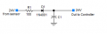
I have checked / tested the connections on the gate control unit for the sensor; there are 3 wires for the sensor, one is +ve supply, 1 is -ve supply, and the 3rd is the input connection from the sensor to the control unit. During normal operation there is a continual 24v DC supply to the sensor, as well as from the sensor to the control unit. When the sensor is triggered, the input from the sensor will drop to 0V DC, and stay at 0v DC until whatever is triggering it is removed.

My initial thoughts (and hitting up Google) was to create some form of timer using a 555, but I am not sure if this would work as I need to detect the duration the sensors have been triggered for, not just start a timer once they have been triggered. The other idea was to use a capacitor / resistor type setup, which would require a certain time to charge the capacitor before it would trigger the control unit, but this all got too complex for me, due to the 24V DC and potentially needing to invert the 0V DC to get it to function.

I am hoping someone with much more of an idea than myself is able to assist, and possibly provide some guidance in terms of how to go about resolving the issue. I don't want to use programmable circuits if possible. I have also already contacted the manufacturer of the gate opener, and they said they haven't got anything "off the shelf" which would help in this scenario.

Apologies if this does not make sense, and any info / assistance will be greatly appreciated!!

Thanks,
Shane.
 

MisterBill2

Joined Jan 23, 2018
27,164
OK, so first I will explain my understanding of the requirement, in case I got it wrong..
When a car approaches the gate and stops, the gate will open because the car has been approaching and stopped for perhaps three seconds. During those three seconds the sensor output is held low, and the gate will open for the car to pass thru.

So what you need is a 24 volt timer that can start and run while the sensor is triggered and it's output pulls low. That is simple: The timer positive supply terminal connects to your 24 volt supply, and the sensor output ties to the timer other terminal. So as long as the sensor detects something the timer will run. The timer needs to have SPDT contacts, that transfer when the time is up. The gate control input connects to the contacts common, the NC contact connects to the +24 volts, and the timer NO contact connects to the 24 volts supply common.
So when the sensor sees nothing, the timer does not run because of no connection of the return. When the sensor detects a bird the timer starts, but after the bird leaves, the timer resets and the contacts never transfer. But when a car arrives the timer starts and runs until the time interval ends and the contacts shift and connect the controller to the common, starting the gate to open.
Very simple, needs only a timer, and no electronic assembly. The big requirement is that the sensor be able to source enough current to operate the timer.
 

MisterBill2

Joined Jan 23, 2018
27,164
My suggestion in post #2 is simpler than those circuits and quite a bit easier to use, Or are you unable to visualize the five connections to a common timer relay module??
 

MisterBill2

Joined Jan 23, 2018
27,164
It is a generic 24 volt powered timer.It operates a set of contacts when the time period has passed.
I do not research products for others. I recommend the specific functionality, I do not do the whole project for free.
 

LesJones

Joined Jan 8, 2017
4,511
If the sensor is an optical beam break sensor then I suggest having two sensor beams space so a bird is not big enough to break both beams at the same time but the car would break them both. If the output of the sensor is a set of normally open contacts then just connect the contacts in series. (So that both contacts have to be closed at the same time.)

Les.
 

MisterBill2

Joined Jan 23, 2018
27,164
If the sensor is an optical beam break sensor then I suggest having two sensor beams space so a bird is not big enough to break both beams at the same time but the car would break them both. If the output of the sensor is a set of normally open contacts then just connect the contacts in series. (So that both contacts have to be closed at the same time.)

Les.
The TS has already mentioned that it is a PIR sensor, not a beam break device.
Now somebody who is used to searching for specific function modules needs to find the TS a 24 volt timer with a relay output that has at least one set of SPDT contacts.
Seepost #2 for a description of the application and the timer requirements.
 

Thread Starter

Sdsaibot

Joined Sep 26, 2020
6
Hello,

Firstly, I would like to say thank you to everyone who has provided their knowledge and suggestions for an approach!! It is truly a fantastic thing to see people are still willing to offer support, even for people they do not know!!

Secondly, I would like to say (while doing my own version of a "happy dance"), using the circuit diagram provided by SGHIOTO, I have been able to put together a circuit which appears to be working... I technically haven't fitted it to the gate opener as yet, but using an LED to show what the output is doing, I think we have a winner!!

Hoping to get it all installed in the next week or so, once I solder the circuit properly onto a board etc. Cannot wait!!!

Thanks once again to everyone for your suggestions, they were greatly appreciated!!!

SD.
 

LesJones

Joined Jan 8, 2017
4,511
I'm not sure if a delay will solve the problem. This is beacause PIRs detect movement so I don't think it will detect the car while it is stationary.

Les.
 

Thread Starter

Sdsaibot

Joined Sep 26, 2020
6
Which circuit are you referring to?
I went with the transistor circuit shown in your first post, as I had most the components already; the only one I didn't have was the FET, so I changed it to a 2N7000.

Just noticed the circuit diagram has changed a bit, compared to the original... Is this a more efficient way of making the circuit, or was there an issue with the previous one??
 

sghioto

Joined Dec 31, 2017
8,633
Correct, I did delete that previous version.
Either one is probably fine.
I have another circuit using a relay if the other ones won't work
Let me know if it works out.
1729981712329.png
 

LesJones

Joined Jan 8, 2017
4,511
Repost #13 Using a 2N7000 in place of a BS250 will not work as a BS250 is P channel and a 2N7000 is N channel.
(This is like replacing a PNP transistor with an NPN transistor.)

Les.
 

sghioto

Joined Dec 31, 2017
8,633
Les, the original circuit the TS was referring to in post #3 was later edited by me in favor of using a P channel mosfet switch.
It used a BS170 N channel which he replaced using the 2N7000 is all.
Apologize for the confusion.
 
Last edited:

Thread Starter

Sdsaibot

Joined Sep 26, 2020
6
Hey sghioto,
I must be upfront offer my sincere apologies, as I think I stuffed up…

As per my previous comments, I made the circuit you designed, which bench tested perfectly; I then added a couple of diodes and LEDs and installed it to the gate opener control board. Unfortunately it did not work, and it appears to have been due to my incompetence….

I provided the incorrect information when explaining how I thought the output from the sensors went low when triggered.

i retested today - with the red lead from the mm placed on the 24vdc supply, and the black lead on the output from the sensors, there was no reading; but when the sensors were triggered there was a reading of 24vdc (actually more like 28vdc). what I think it does is have an open circuit until triggered, and when triggered isupplies the ground to the circuit (if that makes sense)…

Hate to ask, but would you have any thoughts on how to accomplish the goal of making the trigger require a longer time before activating???

Any info would be greatly appreciated, and my apologies again for wasting your time!!

SD
 

MisterBill2

Joined Jan 23, 2018
27,164
I suggested a simple solution in post #2, but I did not supply a circuit and model numbers for the simple timer. Probably Grainger offers such an item. And there are a lot of other electrical parts suppliers that can sell such a product, as well. Didn't anybody even think about that option?? Or is it that nobody understood it because the explanation was not adequate??
Consider that it did not require any circuit assembly, just connecting an available timer device.
 

sghioto

Joined Dec 31, 2017
8,633
i retested today - with the red lead from the mm placed on the 24vdc supply, and the black lead on the output from the sensors, there was no reading;
That would indicate there is 24 volts when not activated and 0 volts when activated as originally discussed.
Standard procedure is to place the black lead on Ground or negative side of the 24vdc power and red lead on the output of the sensor. Try that and see.
I need to know where you connected those diodes and LEDs as that might be the problem.
 
Last edited:

Thread Starter

Sdsaibot

Joined Sep 26, 2020
6
Hey sghioto,

I think I tried the red lead on the output from the sensor and the black lead on the constant negative, but I didn't get a reading, for both scenarios (sensor triggered and sensor not triggered). This was why I tried the red on the 24v constant supply and the black on the output from the sensor, as I thought it might be using the negative as the switch (so to speak). I didn't get any reading when the sensor was not triggered, but as soon as the sensor was triggered it went to 24v...

As for the diodes, I just placed a 1n4007 on both the 24v VCC and the input from the sensor, as I was concerned I might blow up something on the control board or the sensor. The LEDs (and 1.2k resistors) were placed after the diodes; 1 to show the circuit had power and the other to show there was power supplied from the sensor etc. It all worked perfectly at home, but did not work when fitted to the gate opener (which I am assuming is because I didn't test it properly the first time, and it doesn't actually have +24v when not triggered) :( :( :(

I think I will go back tomorrow and test it all again, just to make sure I have my facts right this time... I would do it now, but it is 0200 in the morning, and it takes me an hour to drive there!! :p

Hey Misterbill 2,

Sorry, I should have replied to your comments previously, especially since you went to the trouble of providing support!! Unfortunately, I did not really know what you were talking about to be honest, plus I enjoy making circuits, to try and learn a little more, hence I went straight to the reply containing a circuit (which I seem to have buggered up anyway). I also live in Australia, so we don't have any "Grainger" stores around here, we are lucky to even have 1 store which sells electronic parts (Jaycar); it is roughly a 40min drive for me to get to Jaycar, therefore I was hoping to try and re-use some of the components I have on hand.
 
Top