Delay on circuit without a reset button

Thread Starter

DavidYoung

Joined Mar 23, 2025
15
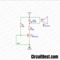
Hello. I'm playing around with this delay-on circuit. It seems to do what it is designed to do. However, I would be grateful if anyone here could tell me how to adjust it to do what I thought it was supposed to do.

I would like to make the buzzer sound a certain time after I connect the power. I don't want it to sound when I connect the power, then turn off when I press reset and then wait the designated time and sound the buzzer again.

Would it be a completely different circuit I would need to build for the thing I am after or could I adjust this one?
 

Attachments

MrChips

Joined Oct 2, 2009
34,627
Let's see if I understand what you are asking.
Apply power. Emit a buzzing sound for t-seconds.

You can do this with a 555-timer circuit.
You can also do this with a simple RC circuit and a driver transistor.

Be aware that there are two types of piezoelectric devices:
1) a piezoelectric transducer that requires an oscillator circuit in order for it to produce sound,
2) a piezoelectric buzzer that has a built-in oscillator. All it needs is DC voltage input to produce sound.
 

AnalogKid

Joined Aug 1, 2013
12,043
Let's see if I understand what you are asking.
Apply power. Emit a buzzing sound for t-seconds.
Disagree.

I would like to make the buzzer sound a certain time after I connect the power. I don't want it to sound when I connect the power,
Granted, the description is ambiguous. My read:

Power on
Wait
Buzz - continuous
Press Reset - Buzzer off
GOTO Wait

1 - R and C for timing
1 - SPST Reset switch
1 - Transistor (or hysteretic gate for a more crisp turn on)

ak
 
Last edited:

Thread Starter

DavidYoung

Joined Mar 23, 2025
15
Thanks. It's AnalogKid's description that is what I am looking for.

Plug in the battery.
After a pre-set time, the buzzer sounds, or whatever circuit I put in its place.
I'm happy to do away with the reset switch, by the way.

Is it a straightforward piece of rewiring? My last experience with electronic theory was A-level physics in the late 1980s.
 

sghioto

Joined Dec 31, 2017
8,633
Thanks. It's AnalogKid's description that is what I am looking for.

Plug in the battery.
After a pre-set time, the buzzer sounds, or whatever circuit I put in its place.
I'm happy to do away with the reset switch, by the way.
After first reset what is your intention of restart?
 

Tonyr1084

Joined Sep 24, 2015
9,744
So you want a buzzer that sounds (let's say) 10 minutes after power is applied and not before. THEN when the buzzer sounds you want to press a reset button which starts another 10 minutes period before the buzzer sounds again. For however long you want to continue doing this - seems it can get tedious. But if that's what you want - - - . Does this describe the desired result? If so then all you need to do is short the cap (C2) momentarily and let the timing period start all over again.
 

Thread Starter

DavidYoung

Joined Mar 23, 2025
15
Basically, I would like to attach a battery to its connector and then have my next circuit (in place of the buzzer) turn on five minutes later.

Am I barking up the wrong tree with this circuit?
 

AnalogKid

Joined Aug 1, 2013
12,043
Basically, I would like to attach a battery to its connector and then have my next circuit (in place of the buzzer) turn on five minutes later.

Am I barking up the wrong tree with this circuit?
Maybe. 5 minutes (300 seconds) is a long time for a simple R-C timer circuit of any flavor. That is a 330 uF capacitor and 910 K resistor. An issue is that the leakage current of such a large capacitor can be a significant fraction of the charging current, and cause inaccuracies in the timing. What is your +/- tolerance in that 5 minute number?

A popular, but more complex option for a long delay circuit uses a CD4060 CMOS logic chip. It has an oscillator and 14-stage divider. In your case, it would reduce the size of the timing (oscillator) capacitor by a factor of approx. 1000. The divide ratio is over 8000, but there are other circuit requirements that prevent reducing the capacitor that much. Still, there is a huge difference in accuracy and stability between a 330 uF aluminum electrolytic and a 0.33 uF film capacitor. +/-10% or +/-20% versus +/-1%.

ak
 
Last edited:

Thread Starter

DavidYoung

Joined Mar 23, 2025
15
In answer to the earlier question, and if it helps in tracking down the ideal circuit diagram, this is what the combination of the two circuits should do:

I attach the battery and either a light-activated or a wire-break alarm is primed, after I have around five minutes to put the alarm in my soon-to-be-unattended bag or to close the door with the wire contact.

The circuits should be able to last for as long as a PP3 battery lets them.

I already have the working alarm circuits.
 

Tonyr1084

Joined Sep 24, 2015
9,744
Almost always someone says "Welcome to AAC." Since nobody has said it yet - myself included - Welcome to AAC.

Speaking for myself only, it seems this project is becoming ore complex. Alarms ? Light activated? Wire break activated? This is where details are even more important. If you can outline the whole project instead of telling us the minimum possible we can help you come to the right circuit.
 

Thread Starter

DavidYoung

Joined Mar 23, 2025
15
No, definitely not. It's for when I have to be a few doors down a corridor and my laptop bag isn't. The wire-break one is for my flat. Its circuit is attached. The light-activated one is a circuit I bought as a kit on eBay, but I can't find the diagram at the moment.

Would it be simpler if I used a relay instead?
 

Attachments

sghioto

Joined Dec 31, 2017
8,633
First suggestion combining the two circuits.
Do you really need the timer if the wire loop is closed before power is connected
1742762351138.png
 
Last edited:

Thread Starter

DavidYoung

Joined Mar 23, 2025
15
The wire loop would be broken when I open my front door to leave. It would be closed again when I shut the front door. During that time, I don't want the alarm to go off. Similarly, although I could fumble around attaching the battery to the light circuit with the annoying squeak the buzzer makes (annoying enough for others to find out who is messing around with other people's bags), it would be easier if I could see what I was doing then zip up the bag and leave it.
 

Tonyr1084

Joined Sep 24, 2015
9,744
No, definitely not. It's for when I have to be a few doors down a corridor and my laptop bag isn't. The wire-break one is for my flat. Its circuit is attached. The light-activated one is a circuit I bought as a kit on eBay, but I can't find the diagram at the moment.
Basically, I would like to attach a battery to its connector and then have my next circuit (in place of the buzzer) turn on five minutes later.
Sorry for me being confused, but in post #1 you showed a circuit with 5, 10, 15 and 20 minute delays. You clarify the desire for a 5 minute delay. Then you say this is an alarm is activated when someone takes your laptop (per-say). Does this mean you want to give a thief a 5 minute head start after nabbing your laptop?

If memory serves it seemed like you wanted a time delay that after that delay period an alarm would sound. Then you push a button to cancel it for another delay period. At first I thought you wanted a repeating alarm every five minutes - since you mention "five minutes".

This is why I'm confused on what you're trying to accomplish.
 

Thread Starter

DavidYoung

Joined Mar 23, 2025
15
It's five minutes to activate the alarm. With the light circuit, that can be done before I leave the room (I'm a language teacher, by the way, and occasionally being summoned a few rooms down a corridor occurs).

One thing I have probably caused confusion over is that my version of the timer circuit only has the five-minute resistor, and no switch at the S3 point. Sorry for not pointing that out to begin with.
 
Top