question for the seasoned

Thread Starter

fredric58

Joined Nov 28, 2014
252
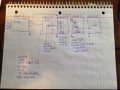
OK, I tried experiments with PWM. they won't work. I can't slow the motor down enough. thinking servo.....(geared down, high rpm little movement) what I want is, think of a clock (second hand of a clock and 12 o'clock is center. servo starts a 3 second mark pauses and moves to 57 second mark, pauses....moves back to the 3 second mark....repeat. BUT, I don't want it to run continually.

the timer circuit I built allows for (2) pauses, one built in (3seconds) and the other is variable (determined by the trim pot). which only allows for a 3 second "run" and a variable pause. or a variable run with a 3 second pause.

in other words, I want this dog to shake his head NO, then be able to make him stop for a specific amount of time and then start over. I think I can accomplish the first part with a 555 timer. I have seen them alternate between 2 LED's and notice the circuit is actually in reverse (the LED's are turn around so the current goes the other direction which could facilitate reversing the servo?

the 556 circuit I built ALMOST facilitates what I need but can the 3 second pulse be extended by changing capacitors?

will have results on the 56K parallel with the 2.2 Monday afternoon.
 
Last edited:

Alec_t

Joined Sep 17, 2013
15,121
I'm afraid you've lost me. What dog?
so the current goes the other direction which could facilitate reversing the servo?
Not if you're using a standard servo. They are controlled by pulses of width 1ms-2ms repeating every ~ 20ms-50ms. 'Centre' = 1.5ms.
can the 3 second pulse be extended by changing capacitors?
Yes.
 

Thread Starter

fredric58

Joined Nov 28, 2014
252
I posted my timer relay schematic earlier, as of now, as designed it has a 3 second pulse and a variable "wait" period dependent on the trim. how do I increase the 3 second pulse to 6 and still keep the variable?
 

Thread Starter

fredric58

Joined Nov 28, 2014
252
Hi, I am back from a month long field test with the prototype you have assisted me with. It works....to some degree. Being the first time out I wasn't expecting perfection. It needs some mods. The biggest problem is POWER CONSUMPTION. so my thoughts are......with the existing circuit. Can it REMAIN a dark sensor activated, AND.....be MOTION ACTIVATED? In other words, It will only operate at night and only POWER UP when the motion sensor is tripped?

I believe the first part can be accomplished, BUT! here is the killer ? If there is NO ACTIVITY for say 2 minutes, can I make it sleep and have the minimalist of power consumption? or better yet, NO power consumption till it is triggered again?
 

Alec_t

Joined Sep 17, 2013
15,121
The 'dark sensor' and motion sensor will both require some current continuously. Zero current draw is impossible.
What motion sensor do you propose to use? It may well have greater standby current than the present circuit :(.
 

Thread Starter

fredric58

Joined Nov 28, 2014
252
the pir operates from 4.5 to 20v. the output once triggered is 3.3. to 3.5. stand by current, if I read it right is 50 microamps. my current set up is as follows:

1. 12 volt supply
2. your dark sensor-with 9v regulator cicuit
3. a pcb that operates on 9v directly from #2 (10mA on standby) when it is activated by #4, it operates for 20 seconds and draws 40mA [[[[ 20 seconds is a KEY factor]]]]
4. relay (9v) from #2, that activates the pcb. the time between activation is variable
5. relay (9v) from #2, that activates a light circuit, currently for 6 seconds, the time between activation is variable
6. a light circuit

items 3,4 and 5 always have power going to them. i believe, WASTED POWER. the PIR has adjustable sensitivity to distance, and duration of time it will activate a circuit. the objective is to only power this device when someone walks by. the only way I see to do it is to use a relay, powered by the pulse from the PIR to activate all 9v circuits at the same time? what do you think?

NOTE: I may drop #5 relay and use the always closed side of #4 to turn on the light.
 

Alec_t

Joined Sep 17, 2013
15,121
A transistor could probably be driven by the PIR to switch the rest of the system.
When the PIR is triggered, how much current can the 3.5V output source?
 

Thread Starter

fredric58

Joined Nov 28, 2014
252
I don't understand the question.....when the pir is trigger it sends 3.5 volts OUT. this will take you to the specs.

http://www.ebay.com/itm/10pcs-HC-SR...440?pt=LH_DefaultDomain_0&hash=item1e81eaf340

Actually, it would be great if I didn't have to use any relays. they're so expensive and they are mechanical, and make some kind of back ground feedback due to the magnetic field. however, I don't think a push on push off switch can be replaced by a circuit. but I am new to this.
 
Last edited:

Alec_t

Joined Sep 17, 2013
15,121
Ok, that datasheet is helpful (despite the Chinglish!).
Can you sketch a schematic of how your pcb and relays are connected up to the 9V regulator output?
Do you know the coil current each relay needs?
Are you able to solder small surface-mount ICs (~3mm x 5mm outline)?
Where does the push-switch come into all this?
 

Thread Starter

fredric58

Joined Nov 28, 2014
252
basically all circuits run down a buss bar (9v supply),
don't know coil current, info on sketch
everything is on a breadboard at this time
push button switch activates pcb program, program lasts 20 seconds

NOTE: circuit #4 is going to be removed, in its place will be a double throw relay on circuit #3
1 side will be set to 3 seconds and the other roughly 17 seconds to = 20 give or take.
 

Attachments

Last edited:

Alec_t

Joined Sep 17, 2013
15,121
The coil current is ~75mA per relay, according to the datasheet, so you're getting close to the limit my dark-sensor was designed for. Hopefully we can eliminate the relay(s). I have one or two designs in mind, but I'm still unclear exactly what the whole system is ultimately intended to do overall.
I believe the function wanted is this :-
At night only, you want it to trigger a 20 sec program run once in response to sensed movement.
When the program run ends the light should go on and the system should sleep until movement is again sensed.
Can you confirm that?
What turns the light off?
 
Last edited:

Thread Starter

fredric58

Joined Nov 28, 2014
252
Interval Timer.jpeg

almost...at night, when movement is sensed by the PIR, 9v will be supplied to the PCB. the PCB, THEN needs to be triggered. it has at the moment a relay timer circuit. the relay does not supply any power it just completes the circuit when the contact closes for 3 seconds. the PCB then runs its program for 20 seconds. currently I have the timer set up to WAIT for a couple minutes and then do the 3 second pulse closing the contact and the PCB does another 20 second program. SO IT RUNS OVER AND OVER AND.....

the lights run on an identical timer, EXCEPT, I changed the capacitor so it turns the light on for 6 seconds, (closes the normally OPEN contact. POWER DOES run through this relay) and then the timer waits for what ever interval I set it to and repeats. IT RUNS OVER AND OVER....

I am sure it can be simplified. the lights CAN operate for the SAME 20 seconds the PCB is running. THE LIGHT CIRCUIT it designed to run on 9v.

I will set the duration for the PIR to ___?____( I don't know yet) seconds so it wont bump the signal to the PCB relay as that would turn it off. it is a push on push off switch. once the relay closes for the timed 3 seconds and starts the PCB program, if the relay gets triggered AGAIN, it will STOP the program.

so timing is important, but I have very wide latitude with the relays trim pots.
 

Thread Starter

fredric58

Joined Nov 28, 2014
252
after sleeping on it, I found a challenge, well maybe. FORGET the light circuit for now. THIS PART IS way more important! here is the consideration. AS IS the timer circuit must have a 24 second interval before it does the 3 second pulse. so.....when the PIR senses something it is going to power the pcb, but it is going to have to wait at least 24 seconds for the timers 3 second pulse to activate it. that is terrible. what I need to accomplish is. PIR senses - powers PCB - 1 second later push on switch is pushed and PCB cycles its 20 second program. the PIR activation length can be set to 25 seconds so it would not retrigger till the PCB is finished. if there was only a way to complete (close) a circuit with electronics without adding or subtracting current, THAT would be awesome!

I thought about just permanently closing the start switch so when the board (pcb) is powered on it will run its cycle and stop. the pir would shut off the power and next time it senses something it would power up and run again. however, the circuit is not designed that way even though it will work. I am afraid I might ruin the pcb. and yes I have fried a couple.

I hope I am explaining this ok?
 

Attachments

Last edited:

Alec_t

Joined Sep 17, 2013
15,121
if there was only a way to complete (close) a circuit with electronics without adding or subtracting current, THAT would be awesome!
Should be doable (at least, with little difference to the current consumption), but we need a schematic of your pcb to see if there's another way of triggering it (other than by using a relay).
 

Thread Starter

fredric58

Joined Nov 28, 2014
252
no schematic available, but I found this, similar concept, and he mentions using a transistor to trigger it. though it is using an ardwino??


Alec_t

Joined Sep 17, 2013
15,121
Ok, so if you can identify which of the two trigger switch connections is ground (battery neg) you just need to connect the emitter of an NPN transistor there and connect the collector to the other switch connection point. The 556 can then drive the transistor base via a suitable resistor instead of driving the relay. Relay eliminated!
You won't get much volume from that voice module. Won't it need amplification? If so, the 9V regulator probably won't provide enough current, so any amp would have to get its supply from the 12V rail.

BTW, are you building an intruder detector with barking dog effect?
 

Thread Starter

fredric58

Joined Nov 28, 2014
252
it is "sorta" an intruder detector, a very quite one, no amplification required.

connections can be identified. this is similar to my first experiment/idea I had before I became a member though I couldn't quite figure out how to do it. I am still faced with a timing problem. the 556 requires 24 seconds before it (a) closes the relay for 3 seconds), or (b) activates the. transistor. every pulse either stops, or starts the program. in 24 seconds the target will be approximately 100 feet away. I could power the pcb directly from the 9v reg circuit as it would remain in stand by mode and use the pir for the trigger. HOWEVER, if I set it (pir) to operate for 24 seconds, it will in affect have a 24 second "pulse" which is basically the same thing as permanently closing the activating switch.

to me....that start push button is like a latch switch, you push it, it closes something, it runs, and when it is done it opens again. this is still FUN, still FASCINATING and FRUSTRATING
 

Alec_t

Joined Sep 17, 2013
15,121
every pulse either stops, or starts the program
I thought sound modules typically had no stop control; they just played the whole recording. Can you post a link to the spec for your module? And a mod to your timer may be possible, to avoid the 24 sec delay.
 

Thread Starter

fredric58

Joined Nov 28, 2014
252
yes, if you push the button and start it, it runs. if you push it again before it is finished it stops.

I would like to use the pir I gave you the link to, the dark sensor 9v reg and simply power the pcb. I am just going to close the circuit, it will still stop after it runs, and will start when powered back up

from the regulator circuit 9v will go to the PIR, the PIR output will need a resistor that will go to the base of an npn, the arrow goes to ground, the other to the neg of the PCB, and I will also need 9v from reg to go to the PCB, can I use a bc547? and how do I figure the resistor?
 
Top