Facebook
 Google
 GitHub
 Linkedin
I'm not surprised. R6 and R7 are selected to give an output voltage of 9V to the load, so the circuit (in particular Q1 and Q2) needs a supply voltage greater than 9V. The circuit was designed for a 12V supply. You've just learned another lesson: if you don't operate a circuit as designed it won't work as designedI didn't make it work today
") .
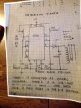
.Test one stage at a time. Using your 9V supply temporarily, shade the photocell so that just a small amount of light gets to it (i.e. simulate twilight). Connect your digital meter (on its 10Volt range if you have that) between pins 2 and 12 of U2. Now twiddle Trim1. You should find a point where the meter reading changes from ~9V to ~0V.what should I try next?