question for the seasoned

Thread Starter

fredric58

Joined Nov 28, 2014
252
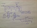
Looking at the "light PIR 9v Reg circuit, I believe the critical components are going to be R3 and R4, REG1 and R6, R7 and R8? the 339 simply "compares". the "PIR" circuit simply "sends" the current?, R3 and R4 divide the voltage to the base of Q1? The "REG" is a little tricky for me as it is a shunt? however R6, over R7 and R8, ALSO work as a voltage divider? That regulate voltage output? I use a trim for R2 but HOW do I figure that into the equation, as it is "variable" and there is the added fact that power comes off #2 of the comparator.
 

Thread Starter

fredric58

Joined Nov 28, 2014
252
Alec, please tell me which resistors to change and values to make this 9v to 5 v. I will have a comparison of the voltage dividers and I think I will better understand how the trim and the reg influence the output. then I think I will be able to make any combination of voltage regulators. thanks!
 

Alec_t

Joined Sep 17, 2013
14,327
I meant simpler because you would need only one regulator. And as you've realised, that would mean just changing a component value or two. I'll look into it and post a revised circuit (or let you know which tweaks are needed).

Edit:
Here you go.
Light-and-PIR-switched-5Vreg.gif
The only changes are to R7 and R8. R8 is eliminated. R7 is now 5k6 to form the correct voltage divider with R6, so that Reg1 gets 2.5V at its control pin.
 
Last edited:

Thread Starter

fredric58

Joined Nov 28, 2014
252
cool and thanks, when I have some time I will "experiment" with different inputs, ex: 18v and try to get say 12v. I think I have enough information for comparison to figure it out. I have also realized, just how much is involved in just the "development" of a circuit and how much problem solving is involved. that's pretty cool too! so here is the realization I just had.

the pir light reg will be of course powered by a battery and it really needs an on off switch, easy enough, a spst would suffice. then I realized "what if I need to check the pcb" meaning need to operate it momentarily without covering the LDR and waving my hand in front of the PIR so it would power up. in other words, BYPASS the PIR and Light sensor and go straight to the regulator circuit.. and temporarily power up the PCB. AH! I think? I can use a double pole, double throw, on/off/on switch. center position the ENTIRE circuit is OFF, UP position the circuit is ARMED, DOWN position 9v would hop over to the regulator circuit outputting 5v and power PCB???????

HOWEVER!!!!!!!!! the comparator has to be taken into consideration. so?????? my temp power of 9v could jump to the collector side of Q3 and that would maintain the reference voltage. then I could add a voltage divider to mimic photocell R1 portion?????? thus allowing a 5v output to the pcb????
 

Thread Starter

fredric58

Joined Nov 28, 2014
252
ok, here is a schematic (sorta) of how I have approached the issue. it is a DPDT switch - on/off/on. in the picture, the one on the left represents the device ON. the one on the right represents only the regulator circuit and the PCB ON. also in parallel to Q1 of the relay is an over ride momentary switch, as this is simply to complete the start circuit of the PCB as no power goes through it. my thought is to. in the switch on the right, send 9v to the trim 1 of the regulator circuit, as this will (=) the current ALREADY established when the whole thing is ON. I believe that I can COVER the LDR when the device is in operating mode and measure the current that goes to pin 5 that establishes the hypersesis (sp?) actuating power output to the PCB. a voltage divider will be required. I can figure that out once I know what current goes to pin 5 when the LDR is in the dark. IN THIS second position the switch, shown as switch 2, the current will not travel any further down the line. therefore isolating the PCB, making it temporarily operational. YES? NO?

my concern with this is, will I also need to break/open the circuit that goes back to the PIR?
 

Attachments

Alec_t

Joined Sep 17, 2013
14,327
If I understand you correctly, you want to use a double-pole on/off/on switch (2P3T) to provide
1) An 'All Off' mode,
2) A normal 'Run' mode and
3) A 'Test' mode in which the PIR and Dark sensor functions are inhibited.

Here's how I'd do it:
Light&PIR&Manual-switched-5Vreg.gif
The two switch halves are shown as S1a and S1b. In the Test mode, Q1 is switched on (hence the regulator is too), the PIR is unpowered, and the comparator output is over-ridden.
 

Thread Starter

fredric58

Joined Nov 28, 2014
252
It took a minute............ but I get IT! yea! I didn't even think about going around the comparator. and it is almost what needs to happen. further down the supply voltage line (5v) I need to break/open/turn off the power to the timer circuit. isolate the pcb completely. perhaps a 3p3T so that in test mode, no power goes to the timer and when in run mode it does. the key is to do it with ONE switch.
 

Thread Starter

fredric58

Joined Nov 28, 2014
252
timer mod results. in theory yes. in practical application, I don't think so. test: volt meter to base of Q1. when power is switched on, using 9v as originally designed, 8.5 volts goes to the base of Q1 almost instantly. nothing else happens. UNTIL you disconnect the power. THEN you can see the cap discharging (very slowly) still measuring from the base of Q1. which would eventually turn it off.

the power snaps on to the base of Q1, but it doesn't snap off.

AH HAAA! I have been experimenting. this is SOOOOOO much fun. here's my simple way of starting and stopping the pcb. the PCB is POWERED at the same throw of the switch a relay is energized, closing the contacts and starts the PCB. the most important part is the contacts "DISCONNECT" when the power shuts off. it doesn't matter that they are closed for the PCB duration. as long as they "DISCONNECT" there is some sort of charge on the pcb, probably a cap? as long as the connection is broken it works fine. just sending power to both the pcb and the relay.

now?????? why not use the PIR pulse (3.5v+-) to energize the base of a transistor switch to replace the relay?? in other words, when the transistor base loses it voltage is there an actual disconnection between the emitter and collector?
 
Last edited:

Alec_t

Joined Sep 17, 2013
14,327
what tests can I run to see if it even works?
Assuming we're talking about the circuit in post #106, just connect your meter (in voltage mode) across the 5V output. In Test Mode Q1 switches on the 5V reg and the meter should measure 5V regardless of whether the Dark sensor indicates Dark or Light and regardless of you jumping around in front of the PIR sensor.
In Run Mode, have your meter across C1 instead. It should measure 9V when the PIR trips and 0V when the PIR is not tripped.
 

Thread Starter

fredric58

Joined Nov 28, 2014
252
no, talking about the timer "mod" circuit. nothing else. I built the circuit, stand alone. powered with 9v. from the original 12v to 9v circuit. I scrapped it, and instead, replaced it with JUST a relay. NOW, when the PIR has a hit, and it is dark, power will go to the PCB AND, to the relay. the PCB is powered up...the contacts close on the relay, which closes the push on switch and the PCB performs. when the pir preset time expires, the power goes OFF. the PCB turns off and the relay contacts disconnect and it is ready for the next time it is triggered. this is what I wanted to accomplish, HOWEVER....I realize, or better, "believe" that this relay (to make it close) sucks a lot of power. it is an electro magnet. (basically)...which brings me back to my very first idea. using a transistor in place of a relay. I believe that if the transistor has a "clean" OFF that it could function in place of the relay. if there is ANY current across from the emitter and collector or vice versa, it will not work! there HAS TO BE a break in current. I'm not sure how the PCB works as I don't have a schematic. but....if a transistor, when it is turned off (no power to the base) will actually break a circuit, it would work. I am going to experiment, there is a transistor used as a switch on youtube. basically a 3.5 battery (PIR pulse) induces the base of the transistor to complete the current path of the LED circuit.
 

Thread Starter

fredric58

Joined Nov 28, 2014
252
good day sir, I made a transistor relay/switch that lights an LED, pretty simple circuit. how ever! some properties change when the transistor was added. the original circuit was a 9v battery an LED and a 330 ohm resistor. now here is the funny part, without the resistor the LED burns up on just 9v. now when I added the transistor to the equation I had to REMOVE the 330 ohm resistor to get the LED to light. which leads me to believe that there is a correlation between the current going from the emitter to the collector and the amount of current going to the base. I don't understand it yet but am hoping I am on the right track and that you may be able to explain it better.

I don't think I actually need the timer but can use the transistor. I'm using the original 9v PCB, new ones haven't arrived. when I power the PCB up I measured the voltage at the trigger switch, it has 4.3-4.5 volts on the hot side. all that needs to be accomplished is to dump it to ground and the PCB will start. I did learn with the ADD-ON circuit (PIR) that what was happening is Q4 gets 3.5 volts and allows Q3 to dump to ground. I don't fully understand how it works but by grounding the base of Q3 it allows current to flow from the emitter to collector. it's like the base of Q3 is a valve? current from the emitter doesn't actually go to ground, but by grounding the base, it's like it OPENS the valve?

so, could a similar circuit as the add on be used, where-in Q3 could be the switch with the 4.5 v of the trigger going to the emitter with the collector going to ground? triggered by another Q4.
 

Alec_t

Joined Sep 17, 2013
14,327
I don't understand it yet but am hoping I am on the right track and that you may be able to explain it better.
I'm afraid you've totally lost me regarding the timer, timer mod, relay circuit and PCB. Can you post a schematic of those parts? It is well-known to use transistors as switches, and a circuit similar to the 'Add-on' I designed could certainly be used to switch on/off such circuits/modules. In general (but there are exceptions) a relay can be replaced by a transistor.
 

Thread Starter

fredric58

Joined Nov 28, 2014
252
yea I have trouble explain stuff sometimes. just a simple question. I have 4.5 v circuit that needs to go to ground. I will hook the 4.5v to the 3904 emitter, the collector will go to ground. what voltage is req' at the base? what is the "equation"
 

Thread Starter

fredric58

Joined Nov 28, 2014
252
i believe the culprit of the transistor is.............................phantom power, there is no complete disconnect that is achieved with a mechanical relay. bummer
 

Alec_t

Joined Sep 17, 2013
14,327
Your proposed connection of a 3904 is wrong. The collector voltage should be greater than the emitter voltage.

You can get almost perfect switching (disconnect) by using a suitable MOSFET. A so-called 'logic-level' type can be turned on fully with a 5V control voltage on its gate terminal. When turned on, it drops only a few mV across its drain-source path. When turned off, the leakage drain-source current is negligible.
 

Alec_t

Joined Sep 17, 2013
14,327
Here's how you could connect a 3904 to switch a PCB or other load of <~100mA :-
SwitchedPCB.gif
The 3.5V trigger signal from the PIR would drive a current of ~10mA through Q1 base-emitter junction, allowing up to ~100mA to flow through the collector-emitter path (and hence the PCB or other load). R2 is included to help 'pull-down' the base voltage to switch off Q1 when the trigger signal is absent, but may not be necessary if the PIR itself pulls the base voltage down.
 

Thread Starter

fredric58

Joined Nov 28, 2014
252
ok....I tried some more experiments with the transistor as a switch.. using a voltage divider I sent less current, same current, and more current to the base of the switch. and yes more current is required.... the transistor switch DOES work, BUT! it works in this manner. when triggered the very first time it actuates the PCB. then here is what happens, the NEXT time it triggers it resets the PCB, the next time it plays, the next time it resets. which leaves a gap between operation. in other words every other time it triggers it functions correctly. when I use the relay every time I send power to the PCB AND the relay, the PCB starts at the beginning of it's program. it can even be interrupted (power off) in the middle of operation but once power is applied it starts up from the beginning. I like the idea of a transistor mostly due to cost, but I can't seem to get the bug out of it.
 

Alec_t

Joined Sep 17, 2013
14,327
We should be able to find a simple workaround. Something else you could try is a so-called 'high-side switch' using two transistors, like this :-
High-side-switch.gif
It might be necessary to add a 10k (or so) resistor in parallel with the PCB, to assist the power-on-reset function which the PCB seeminly requires.
 

Thread Starter

fredric58

Joined Nov 28, 2014
252
hi Alec, I don't think I am explaining this very well. the PCB is powered by 5 volts. that happens because of the PIR-dark sense 5v reg circuit. Inside, or maybe better said, "on board" the PCB is another circuit that carries around 4.5 volts. when this circuit is briefly sent to GND, operation of the PCB begins. IF it is sent to GND during the operation, IT STOPS. if grounded again it will start at the beginning. the problem I am having with the transistor circuit is that every time the transistor switches on the PCB """THINKS"""" it is being turned on, then off, then on. the transistor switch DOES what it's supposed to do. there is just something about the "momentary" ground that's frizzling brain.

I don't have a schematic by I speculate that this "on board" circuit has a cap on it. I say that because if I leave the volt meter on the circuit and disconnect the power to the PCB the voltage can be seen draining down.

the relay I used in the original version, was hooked to the "always open" contact and used as a switch, when it closed briefly for 3 seconds (via the 556 circuit) it would dump the on board circuit to ground then go back to open. it worked well. however more control is desired and the elimination of the relay.
 
Last edited:

Alec_t

Joined Sep 17, 2013
14,327
If I understand correctly then, you want a transistor switch to trigger (temporarily ground) this normally-4.5V input after the 5V power has been supplied to the PCB?
 
Top